Probe device configuration
Probe is configured as type P5 (from RepRapFirmware 1.14 on), a normally closed switch for bed probing between the IN and GND pins of the Z-probe connector (Duet 0.8.5 and Duet 2 WiFi).
For more reference information see Duet3D gcode wiki
This is an example of the relevant config.sys entries:
; Euclid Probe Settings RRF 3.x on Duet2
;
; Endstop type S0 (active low switch) is no longer supported in M574 commands.
; Instead, use type S1 and invert the input by prefixing the pin name with '!'.
; example to have multiple endstops on leadscrews
; M574 Z1 S1 P"zstop+e1stop" ; configure active-high endstops for low end on Z via pins zstop and e1stop
; Make sure that the two endstops are defined in the same order in the M574 command
; as the corresponding Z motors in your M584 command.
M574 Z1 S2 ; configure Z-probe endstop for low end on Z
;
M558 K0 P5 C"^zprobe.in" H8 F300 T9000 A3 S0.01
; K0 for probe 0, P5 for NC switch, C for input pin,
; ^ for enabling the native pullup resistor on Duet 2
; hardware running RRF3
; H dive height of 8mm, F300 probing speed 6mm/sec,
; T9000 travel speed 150mm/sec,
; A3 number of probes 1, S0.01 max tolerance of 0.01
;
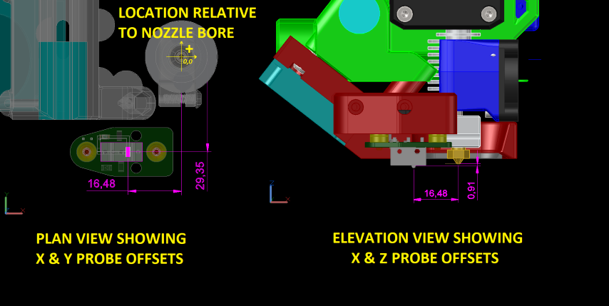
G31 K0 P500 X-16.4 Y-29.4 Z0.90 ; CHECK for LOOSE things first! set Z probe trigger
; value, offset and trigger height. Higher numbers
; makes nozzle closer to bed
; switch plunger is 16.4mm to the LEFT and 29.27mm in
; FRONT of the nozzle. Switch triggers 0.9mm BELOW nozzle
; https://duet3d.dozuki.com/Wiki/Test_and_calibrate_the_Z_probe#Section_Fine_tuning_the_trigger_height
; if you have to move the nozzle away from the bed,
; decrease the G31 Z value by the amount of baby stepping used.
Setting Z Elevation
Narrative is written in general terms, using gcode commands. The process is basically starting with a known Z probe offset and then adding/subtracting the difference of the true and relative positions. Figure on doing it twice- once cold and then hot if you want more accurate height. If you have extrusion remnants on the nozzle, preheat to 130-150C to soften the plastic and wire the nozzle clean.
A feeler gauge of known thickness is needed for this procedure. Examples-
- 20# bond paper is about 0.1mm, or 0.004 inches
- 0.2mm feeler gauge is ideal, 0.008in is close (0.207mm)
- Brass or stainless steel feeler gauges are recommended even though they cost a little more because the stainless steel is non-magnetic and the wont rust.
0.2mm – 1/2″x12″ stainless steel as an example https://www.mcmaster.com/2300A9/ $2.88
0.2mm – 1/2″x12″ Carbon Steel as an example <a href= https://www.mcmaster.com/2283A9/”>https://www.mcmaster.com/2283A9/</a> $1.98 - measure any long and thin object you can manipulate. Bare PCB boards are reliably 1.6mm thick.
- Pokemon cards are reputed to be EXACTLY 0.2mm thick
- Paper matchbook covers are 0.013 inch. or 0.35mm thick. Credit cards are around 0.03 inches, or 0.762mm thick.
-
Assign an initial Z probe offset SMALLER than you will actually use to stop the probe HIGHER off the bed.
In RRFG31 … Z2.5as example. -
Home Z as you normally do.
- Move the carriage to a point on the bed where its going to be easy to access with a strip of paper / feeler gauge.
G1 X100 Y100
- Creep the nozzle down to touch it off on the feeler gauge. If you have a display or machine console, use that to save yourself some work. Otherwise, issue terminal commands to jog down, adjust the move distance to suit.
G91 ; set the machine into relative coordinates mode
G1 Z-0.05 ; move the bed UP 0.05mm
- repeat the small Z motion until you just touch your feeler
- You will feel a slight drag on the feller when the nozzle is touching it. Sometimes you can hear slight changes in hot end fan if its running when the nozzle just touches.
- Once you touch off the nozzle to the feeler gauge, set the machine’s Z position to that height.
G92 Z0.2 ; set the Z axis to be the value of the feeler gauge 0.2 in this example
- Probe the spot you are at. Use a single probe command to report the probe position when it triggers. Pay attention to the G-code options so at to no reset the Z or probe height.
G30 S-1 ; Probe the bed at the current XY position. When the probe is triggered
;do not adjust the Z coordinate, just report the height which the probe triggered.
That reported value is the best starting point to set your Z-probe offset for your system!
You will have to fine tune this a bit either by redoing the procedure hot, or using baby-stepping when you print. It is often easier to print a single 0.45mm wide perimeter, 0.3mm high around the bed and measure it to fine adjust the Z probe height.
You can reprobe the SAME spot a few times and average the values: G30 S-1 for example to probe and report the trigger height. The result is the Z probe offset value to use in your config. In this next example line, 2.956
G31 ...Z2.956
If you really want to get fancy, you can use a g-code macro like this to have the system do it for you probing say 10 points and doing the math.
findZprobeoffset.g
;***
; findZprobeoffset.g
; ***
; the system must be homed before running this macro

; make sure that the nozzle is properly gapped with known height gauge before the start of the test
; Preheat nozzle to 130, clean nozzle, touch off nozzle to 0.2mm feeler gauge, G92 Z0.2

M291 P"Probe will be tested 10 times and return mean and standard deviation. Ok or Cancel?" R"WARNING" S3
; User must click OK or cancel.

M401               ; deploy probe
G1 X100 Y100 Z15   ; travel to X,Y of probe point 15mm above bed
G30 Z-9999         ; probe point 1
G30 Z-9999         ; probe point 2
G30 Z-9999         ; probe point 3
G30 Z-9999         ; probe point 4
G30 Z-9999         ; probe point 5
G30 Z-9999         ; probe point 6
G30 Z-9999         ; probe point 7
G30 Z-9999         ; probe point 8
G30 Z-9999         ; probe point 9
G30 Z-9999 S-1     ; probe point 10, computer average and standard of deviation
G91
G0 Z15
G90
M402               ; retract probe