General klipper firmware setup
We have broken the klipper setup into two parts- the general hardware configuration in the printer.cfg to be consistent with all hardware definitions and a pointer in the printer.cfg to include the euclid.cfg file for the macros. Please look at both parts.
Probe device configuration
Configuring Euclid Probe in klipper is similar to defining and endstop switch. The following is an example of the probe section in the printer configuration file.
For more reference information see klipper Command reference
Below is an example of the relevant printer.cfg entries. Euclid macros make use of force_move and respond.
Macros for probe deploy and stow are covered here.
[force_move]
enable_force_move: True
#   Set to true to enable FORCE_MOVE and SET_KINEMATIC_POSITION
#   extended G-Code commands. The default is false.
[respond]
default_type: echo
#   Sets the default prefix of the "M118" and "RESPOND" output to one
#   of the following:
#       echo: "echo: " (This is the default)
#       command: "// "
#       error: "!! "
default_prefix: echo:
#   Directly sets the default prefix. If present, this value will
#   override the "default_type".
[probe]
## Euclid Probe
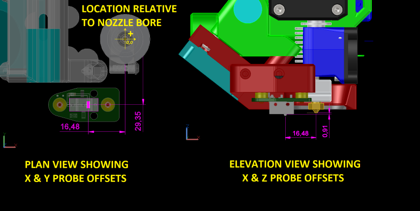
pin: ^P1.24 # ZMax on SKR 1.1
x_offset: -20
y_offset: -2.0
z_offset: 12.0
z_offset:
# The distance (in mm) between the bed and the nozzle when the probe
# triggers. This parameter must be provided.
speed: 5
samples: 2
samples_result: average
sample_retract_dist: 5.0
samples_tolerance: 0.050
samples_tolerance_retries: 3
lift_speed: 30
[include euclid.cfg]
# where euclid.cfg is the filename with all the probe deploy and retract and probing macros
Example files
Here are the examples of euclid configuration files. euclid.cfg files.
Simple Version
00-euclid_exampleV3.cfg is a generic template with hard coded position variables and simple macros. Its pretty human readable in terms of what is going on.
More Advanced Version
Version with more features: 00-euclid_exampleV5.cfg and uses array variables and has more fully featured macros and ties into startup scripts. It takes a bit more work to set up. This version is contributed by yolodubstep, and is a stripped down version of his configs. Yolodubstep’s most current configs are here- Yolodubstep V-Core files..
Pay attention to the ## @TODO statements where user input is required.
The best documented and most comprehensive set of klipper configuration files
The best documented and most comprehensive set of klipper configuration files are from deepsiks for his 350mm Voron 2.4, with BTT Octopus, Bondtech LGX extruder, Phaetus Dragon HF hot end with Bondtech 0.4 CHT nozzle Hall Effect Endstops and Euclid Probe!
deepsiks has done a fantastic job to document and explain what is going on within the files and macros. It’s a great read to learn about the inner workings of klipper.
The other various printer configurations are in the user submitted klipper folder in the Firmware Examples/klipper folder.
Setting Z offset elevation
Narrative is written in general terms, using gcode commands. The process is basically starting with a known Z probe offset and then adding/subtracting the difference of the true and relative positions. Figure on doing it twice- once cold and then hot if you want more accurate height. If you have extrusion remnants on the nozzle, preheat to 130-150C to soften the plastic and wipe the nozzle clean and let it cool.
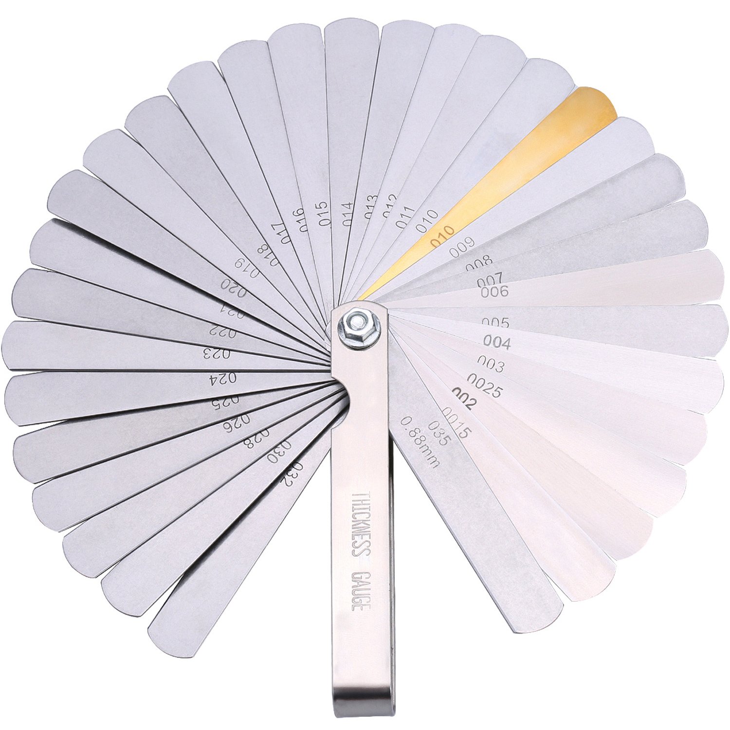
A feeler gauge of known thickness is needed for this procedure! Examples-
- 20# bond paper is about 0.1mm, or 0.004 inches
- 0.2mm feeler gauge is ideal, 0.008in is close (0.207mm)
- Brass or stainless steel feeler gauges are recommended even though they cost a little more because the stainless steel is non-magnetic and the wont rust.
- 0.2mm – 1/2″x12″ stainless steel as an example https://www.mcmaster.com/2300A9/ $2.88
- 0.2mm – 1/2″x12″ Carbon Steel as an example https://www.mcmaster.com/2283A9/ $1.98
- 0.008in 1/2”x12” Brass feeler gauge https://www.mcmaster.com/20385A38/ $3.21
- measure any long and thin object you can manipulate. Bare PCB boards are reliably 1.6mm thick.
- Pokemon cards are reputed to be EXACTLY 0.2mm thick
- Paper matchbook covers are 0.013 inch. or 0.35mm thick. Verify with your calipers
- Credit cards are around 0.03 inches, or 0.762mm thick. Verify with your calipers
Set initial z_offset
Assign an initial Z probe offset SMALLER than you will actually use to stop the probe HIGHER off the bed.
[probe]
...
z_offset: Z5.0
as example.
Home Z
Home Z as you normally do. If you use the probe as Z endstop and probe, go ahead and let it deploy it and home Z, but be ready to abort/halt the printer if things go awry.
- If your macros stow the probe, let it. If not, just remove the probe by hand for the next steps.
Move to a working location with good access
Move the carriage to a point on the bed where it’s going to be easy to access with the feeler gauge. Ideally, this would be the same point you normally home Z to, or the center of the bed (This is one reason for a long feeler gauge).
- Make sure the probe is not attached otherwise it will be in the way.
G0 X150 Y150
Creep the nozzle down
Creep the nozzle down to touch off on the feeler gauge. Issue terminal commands to jog down, adjust the move distance to suit.
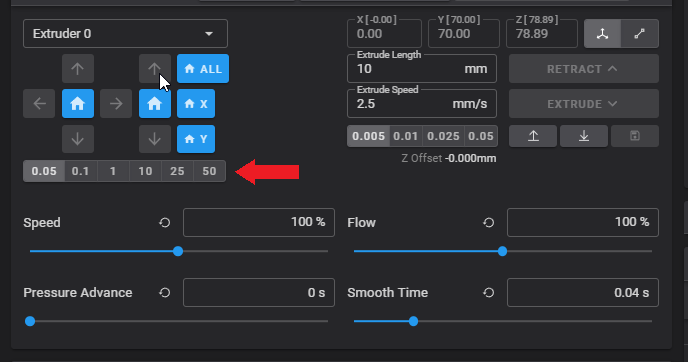
G91 set the machine into relative coordinates mode
G0 Z-0.05 move the bed UP 0.05mm
- Repeat the small Z motions until you just touch your feeler
- You will feel slight drag on the feeler gauge when the nozzle is touching it. Sometimes you can hear slight changes in hot end fan if its running when the nozzle just touches too.
- Once you touch off the nozzle to the feeler gauge, set the machine’s Z position to that height.
G92 Z0.2 set the Z axis to be the value of the feeler gauge 0.2 in this example
Move the bed away from the nozzle and hand deploy the probe
Move the bed away from the nozzle and hand deploy the probe
G0 Z20
G90return the machine to absolute coordinates
Probe the spot you were at.
Probe the spot you were at.Use a single probe command to report the probe position when it triggers. Pay attention to the G-code options so at to no reset the Z or probe height.
G0 X100 Y100 Z15
PROBE
Results
The result will look something like this-
Result is z=7.050000
That reported value is the best starting point to set your Z-probe offset for your system!
edit the [probe] section of the config to reflect the result.
[probe]
pin: ^P1.24 # ZMax on SKR 1.1
x_offset: -20
y_offset: -2.0
z_offset: 12.0
z_offset: 7.05  # this value is from the probe result using feeler gauge to set Z height
#   The distance (in mm) between the bed and the nozzle when the probe
#   triggers. This parameter must be provided.
speed: 5
samples: 2
samples_result: average
sample_retract_dist: 5.0
samples_tolerance: 0.050
samples_tolerance_retries: 3
lift_speed: 30

[include euclid.cfg]
# where euclid.cfg is the filename with all the probe deploy and retract and probing macros
Move bed
Move the bed away from the carriage.
G0 Z20
That reported value is the best starting point to set your Z-probe offset for your system!
Final tweaks
You will may to fine tune this a bit either by redoing the procedure hot, or using baby-stepping when you print. It is often easier to print a single 0.45mm wide perimeter, 0.3mm high around the bed and measure it to fine adjust the Z probe height.
More advanced probe settings and configurations are covered in the klipper Command Reference in the section Probe calibration