Build Instructions
Reminder that community discussion and support is available as a subgroup to the CroXY Discord 
License

This work is licensed under a Creative Commons Attribution-NonCommercial-ShareAlike 4.0 International License.
How to get Euclid Probe
The gerbers for DIY boards are hosted at OSHPark and Aisler. They are the same circuitry as the production version. These PCB’s are the original design where the same PCB can be used for the tool board or probe board. We try to update them as we update the other boards to be consistent. There is no difference in the shared gerbers at either OSHPark or Aisler. The rest of the suggested parts are listed in the BOM. We understand that the availability for some of the specified parts has recently become difficult- this affects us too.
A note about the relative differences in source pricing- Aisler costs run a little higher because they donate a portion of their profits to KiCAD development at CERN. We use KiCAD and don’t mind paying a little more for this. The production of Aisler boards also seems to be done in the EU and then get shipped to other parts of the world. OSHPark is made in Oregon, USA and shipped as well.
No part of these purchases at OSHPArk or Aisler benefit the creators of Euclid Probe. There are no affiliate links or royalties paid on these transactions.
OSHPark.com https://oshpark.com/shared_projects/3qYUvroW
Aisler https://aisler.net/p/PHODHLTM
Assembly Instructions
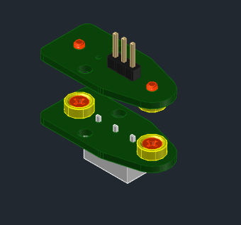
The same PCB is used for both the upper and lower half, and uses
- 4, 1/4x1/8 axially polarized magnets,
- SPDT snap action switch,
- M2 & M3 mounting screws,
- and some other random bits and bobs you probably have laying about.
The parts list specifies a snap action switch. Almost any subminiature switch will work. The circuit only uses the Normally Closed (NC) half of the switch as a momentary pushbutton. Testing has shown that other switches of the same package size will work and their repeatability is good enough for use as a Z probe.
Reliability testing has shown name brand switches to have a standard of deviation of the trigger point on the order of 0.002mm, and no-name aliExpress and ebay generics to be be 0.004mm- a full order of magnitude better than BLTouch and inductive probes and similar variants. C&K, Wurth, Honeywell, ZF, Crouzets, Panasonics. All will work great as probe switches.
The operating temperature range of most mainstream switches of this class are 80°C, so theoretically the probe should function in a heated chamber of at least 60°C.
SMT components are optional on the upper PCB to create visual indicator of switch action. This provides confirmation of probe attachement and probe trigger.
Parts
BOM
- 2 - Euclid Probe PCBs - Same PCB is used for the upper and lower half.
- 4 - 1/4x1/8 axially magnetized countersunk magnets. Two magnets must have N on countersink side, two with S on countersink side. European sources carry 7mm magnets.
- 1 - SPDT snap action switch. The kind found in computer mice, reprap endstops, etc..
- 4 - M2x5 countersunk steel screws to attach the magnets to the PCB’s. (2-56 x 3/8 and M2-8 to 10mm length ok)
- 2 - M2.5 or M3 screws to attach the board to the carriage. Stainless steel button head cap screws (non magnetic) are prefered. Regualr cap screws may an interference issue with the heads being as tall or taller than the magnets.
- 1 - pin header of your choice:
- 2.54mm pitch straight, right angled, Dupont or JST XH connector.
- If using the optional SMT LED indicator, this must be a 3 pins connector.
- 1 - SMT LED- (Optional). Ones with Vf of ~2.2v are best (red, yellow, orange and pale green). Any sized component from 0603 - 0805 - 1206 will work and can be soldered to the pads.
- 1 - SMT 1kOhm Resistor (Optional). Any sized component from 0603 - 0805 - 1206 will work and can be soldered to the pads.
Switch:
SPDT switches may work as long as they match the footprint. Early prototypes were fabricated from recycled Makerbot endstop switches that had damaged levers. They were of generic/unknown origin but worked just fine. NC and CPM terminals need to be at each end.
Magnets
1/4” od x 1/8” thick with countersunk hole for #2 screw, Axially Magnetized so that they stick face to face. Ideally you want magnets pairs so that they mate face to face. Here are some examples in the US and Eu-
-
https://www.kjmagnetics.com/proddetail.asp?prod=R422CS-P-N52
-
https://www.mcmaster.com/5862K223/
-
https://www.magfine.it/it/user_data/neodymium_disc_countersunk.php
Screws for mounitng magnets
Pilot holes in the PCB are sized for 2-56 or M2x0.4 self tapping plastic screws. Where to find 4 of them? Good question! Junked kids toys or electronics. If all else fails, tap it if you have the tools. Otherwise, through drill it and use an M2 or 2-56 flat head screw and nut from the hardware store. A dab of Loctite or super-glue will keep the nut on the screw together nicely. Hobby shops often have these litle screws too.
Trim Craft Aviation RC is a known good supplier for small lots of heatserts and Imperial and Metric fasteners in Steel, Stainless Steel, and Nylon. Trim Craft Aviation RC
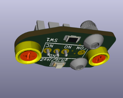
Bottom Board Assembly:
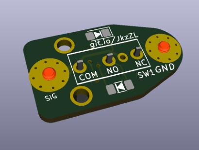
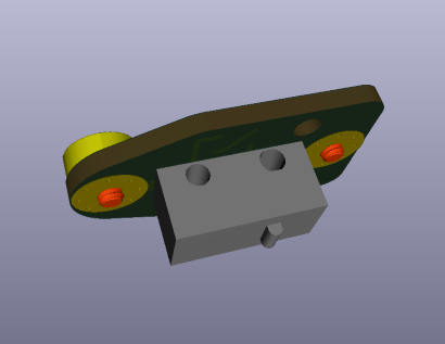
Solder the switch to the board, noting that the switch orientation is such that the COM terminal is towards the rear end of the switch: this is usually the side with the switch plunger.
You can clip the excess tails of the pins if desire. If you are using a right angle header mounted to the underside of the top board, you might need to clip them for clearance. It is suggested that you put on a piece of Kapton tape or similar to insulate the exposed terminals. Nail polish or model enamel works well too.
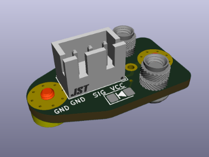
Top Board Assembly:
If not using the surface mounted LED you may use a 2 pin header of your choice soldered to the 2.54mm pitch holes marked GND-SIG, or a 3-pin JST-XH connector in the holes marked GND-SIG-VCC.
Install the two magnets onto the top board with M2 countersunk screws. The magnet’s polarities should be opposite that of the bottom board.
Magnet Attachment
Test out your magnets for their polarity and proper orientation.The magnets area ideally orientated so that their poles alternate fore-aft on the board. This way, when the tool aproaches the probe in the dock, the leading magnet’s polarity is same as the first magnet on the probe it encounters. Since these two magnets are of the same polarity, they are repulsed instead of attracted to each other, and the probe will pass this magnet and only get picked up when the pairs of magnets are aligned.
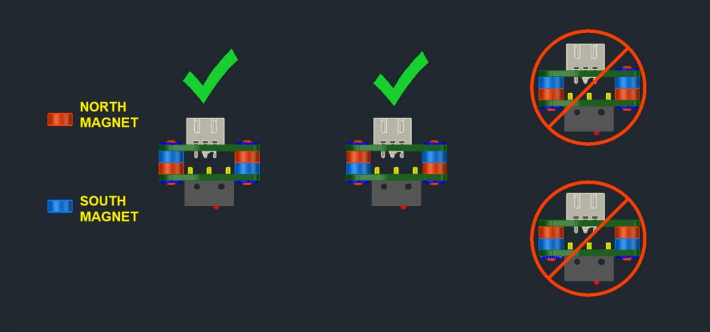
One of the magnets should have N pole up, the other S pole up. Unless they are marked, all you need to do is get two of them to stick together and place another pair adjacent. Put a piece of paper between magnets so that they can be easily slid apart. Try not to let the magnets slam together, they can chip. If the two pairs are attracted to each other, flip one set over-under so that the mating pairs attract, but the adjacent pairs repulse.
Magnets should be cinched down snug to the pads on the PCB. If you are using thru-bolts, you will want to Use a dab of some sort of thread locker for good measure. Loctite is a common example, but you sould also use a drop of nail polish, hair spray, or even white glue when installing the nut. A drop of superglue, (CA) can be dabbed to the screw at the nut were it sticks out as well.
Mounting the Top Tool Board
The mounting holes in the PCB are sized for tapping the PCB with an M3 tap, else thru drill it for the fastener of your choice. The heatserts shown in the renderings are a suggestion, not a requirement. They were modeled into the design to attempt to maintain adequate material allowance and clearances for their use.
Optional LED’s
The top board can be populated with an LED and resistor to indicate when the probe has triggered. The LED will illiminate when the boards are coupled and the electric circuit is complete. The LED will go OFF when the switch is triggered: the closed circuit goes open. This is intentional and by design.
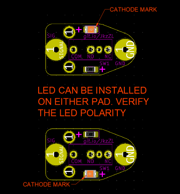
The SMT pads are provided in pairs on both faces of the board. This way, the LED can be located on either side, top or bottom, to provide the best visibility depending on the mounting. The top board requires a VCC connection to power the LED and thus requires a 3 pin header. The LED will not work on the bottom probe board.
Solder an SMT LED to the pad where it will be most visible when triggered. The recommended LED should be a yellow or green one with a low current draw to reduce the load on the controller MCU. Pay attention to cathode mark and the LED polarity symbols as you install it. You can instal the LED on whichever position that suits you best as long as you install the resistor on the remaining pad on that face of the board. Verify the datasheet of your components to ensure the proper orientation. Pads are sized for 1206 SMT components, but it is possible to install an SMT as small as 0603 onto the pads with careful soldering.
If you need a reminder of how the polarity is marked and how the SMT components are marked, a page like this might be helpful. http://www.talkingelectronics.com/ChipDataEbook-1d/html/SM-LEDs.html
Next solder a 1kOhm SMT resistor to the empty pad on the same side of the board. If in doubt as to which set of pads to install the resistor to, probe the LED for continutiy through the vias.