Build Instructions
Reminder that community discussion and support is available as a subgroup to the CroXY Discord 
TL:DR
Open the bag carefully; sort your parts: solder the header and switch; attach your magnets; screw the toolboard to the mount; attach your dock; config your firmware and print perfect first layers happily ever after!
Prepare your kit:
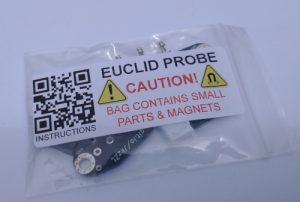
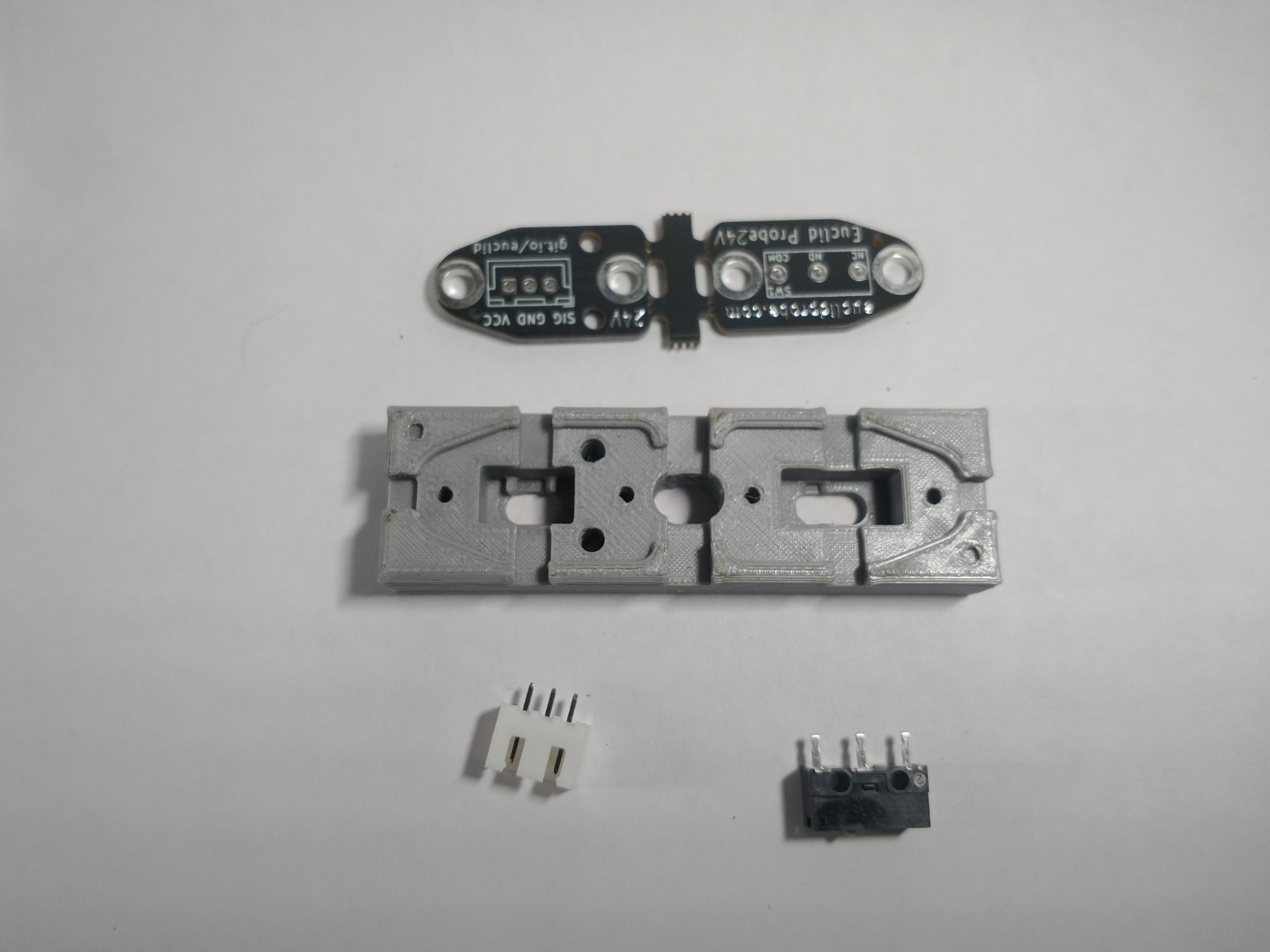
The Euclid Probe kit will arrive in a small zip-sealed baggie. Beware, there are small parts that can be easily lost.
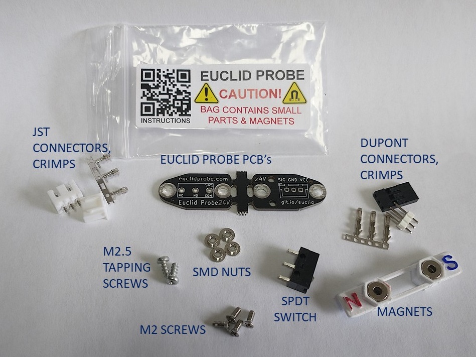
The kit contains the PCB set, screws, SMD nuts, a switch, magnets and wiring connectors. It is helpful to sort and organize the parts.
Step 1 – Board Preparation:
Check the shoulders and sides of the PCB to make sure that they are smooth so that they don’t catch on the the lips of the dock. Once and a while one sneaks through our QA/QC.
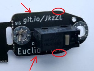
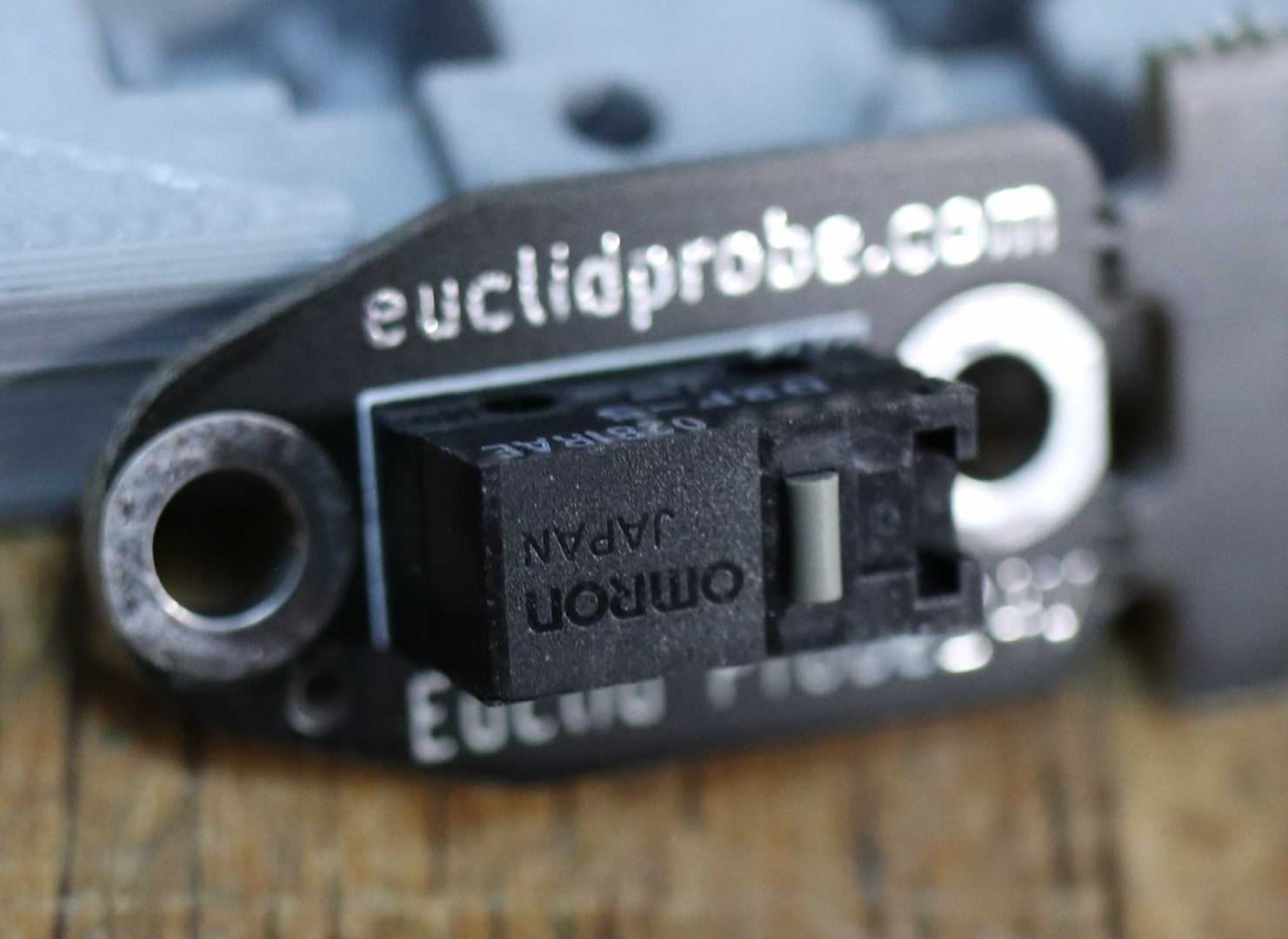
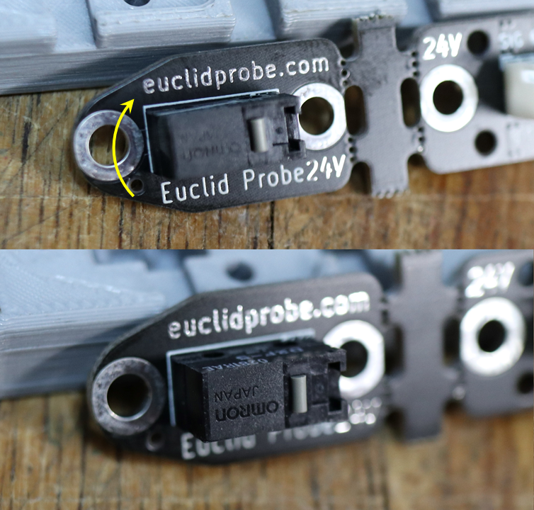
Determine the best orientation for the plunger on the switch:
- Ideally, the switch plunger should be closest to the nozzle when the probe is deployed. Most installations will have the plunger towards the square end of the probe PCB.
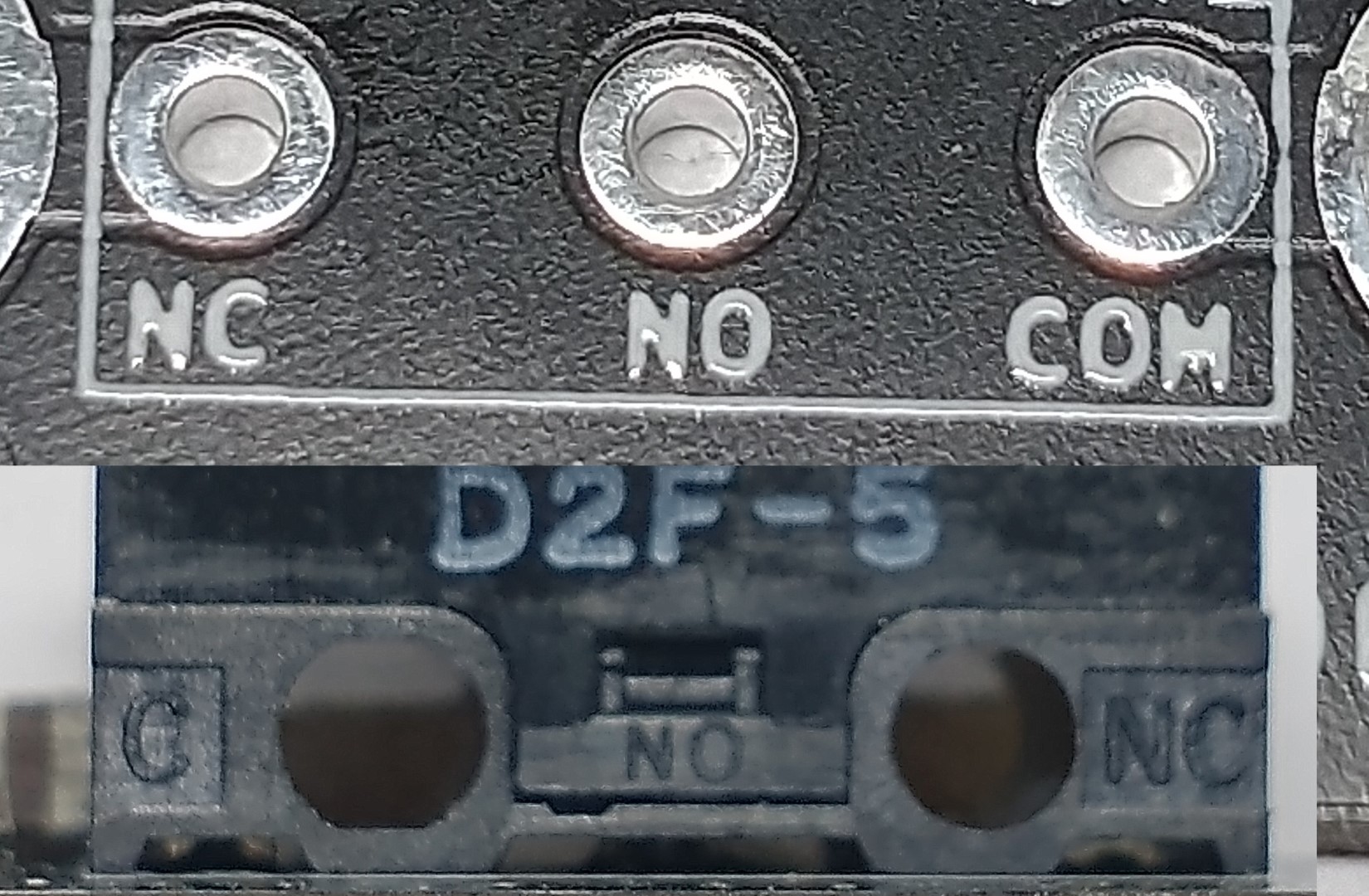
- Note the COM-NC pins on the switch correspond to the holes on the PCB labeled COM and NC. The switch can install either way as long as the COM - NC are paired up .
|
|
- Installations on printers like Ender3 where the tool board and probe board point in opposite directions will benefit from the switch plunger towards the front of the probe PCB, pointing towards the nozzle.
|
|
Determine how you will be attaching the upper tool board PCB to your carriage. The mount holes in the upper board are drilled thru 2.5mm⌀:
- Use the included M2.5 self tapping screws into the pilot holes for the provided mounts.
- Tap the PCB pilot holes with an M3 tap so that you can secure it from above and have concealed fasteners.
- Drill through with M3mm⌀ and use M3 screws to secure to M3 heatserts embedded in your carriage. This is a popular method.
- Countersink for concealed fasteners. There is sufficient material in the PCB to countersink the screw holes to use flat head screws for a flush installation into holes above.
- The holes are positioned such that if heatserts were used in a carriage, there will be sufficient cover in the margins between the JST connector housing clearance hole and the inserts.
Assembly Aid
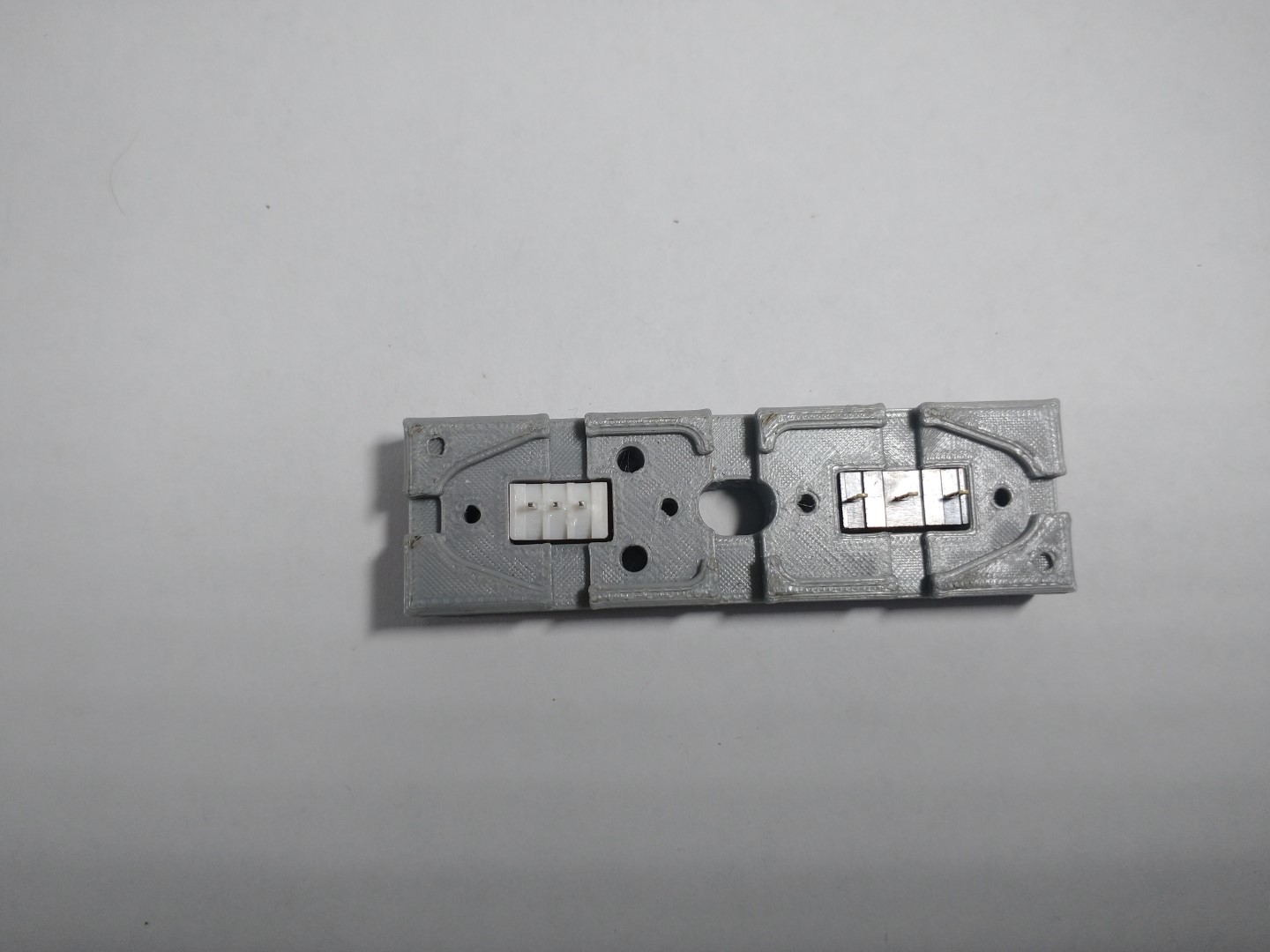
You may want to print out the combined soldering holder & drill-tap guide block that we have designed. It will hold the JST header and switch upright for soldering and as a guide for an M3 tap or 3mm⌀ drill perpendicular to the PCB. User feedback has been that they felt they were more successful by using it than they might have been without.
The differences in stl versions are only the clearances around the outlines.Solder and Drilling Jig with 0.2mm clearance margins is the usual block we recommend for a reasonably tuned printer. It has 0.2mm gap around all components to provide a slip fit.
If your printer or slicer is not well calibrated, you may benefit from the larger clearances- 0.3 or 0.4 version.
The guide blocks are here in the repo.
Dynamic preview of stl for download:
Step 2 - Board Assembly:
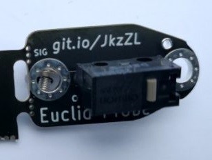
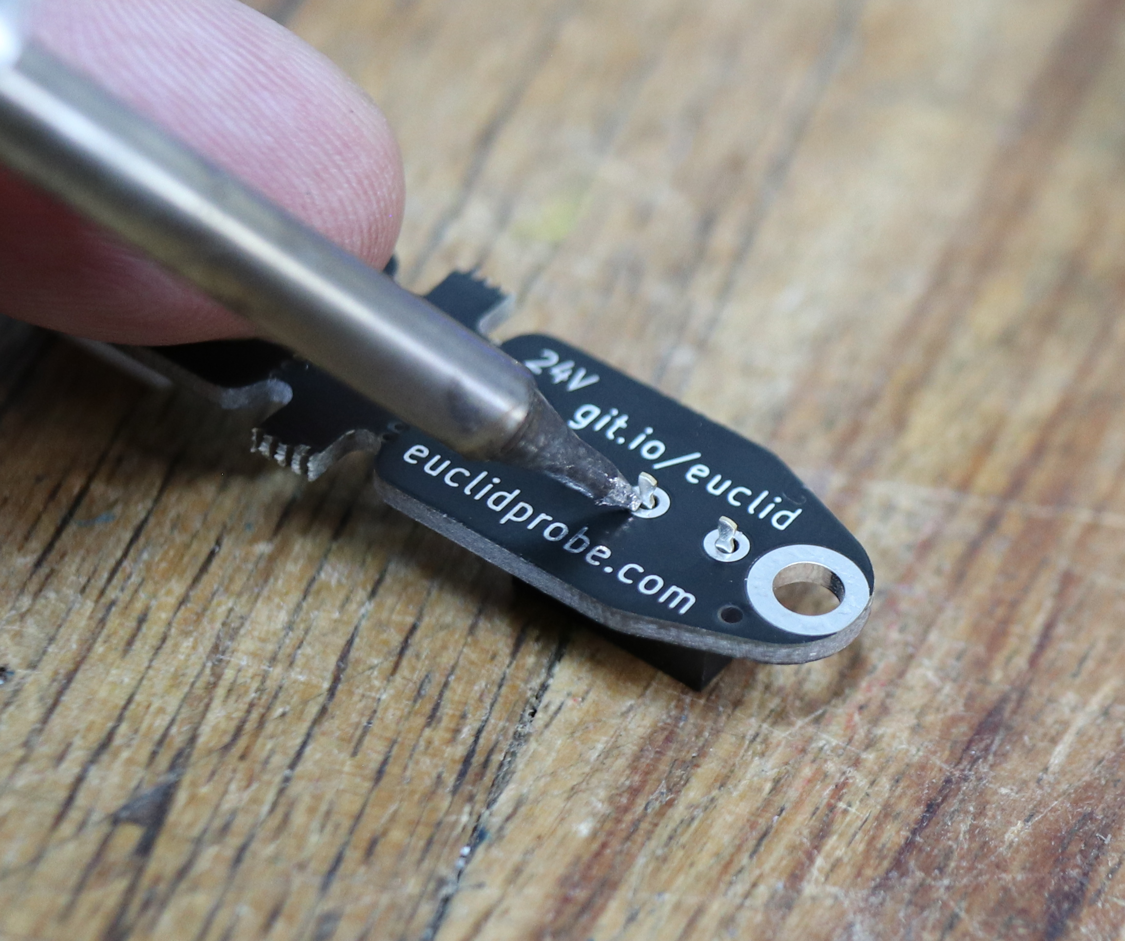
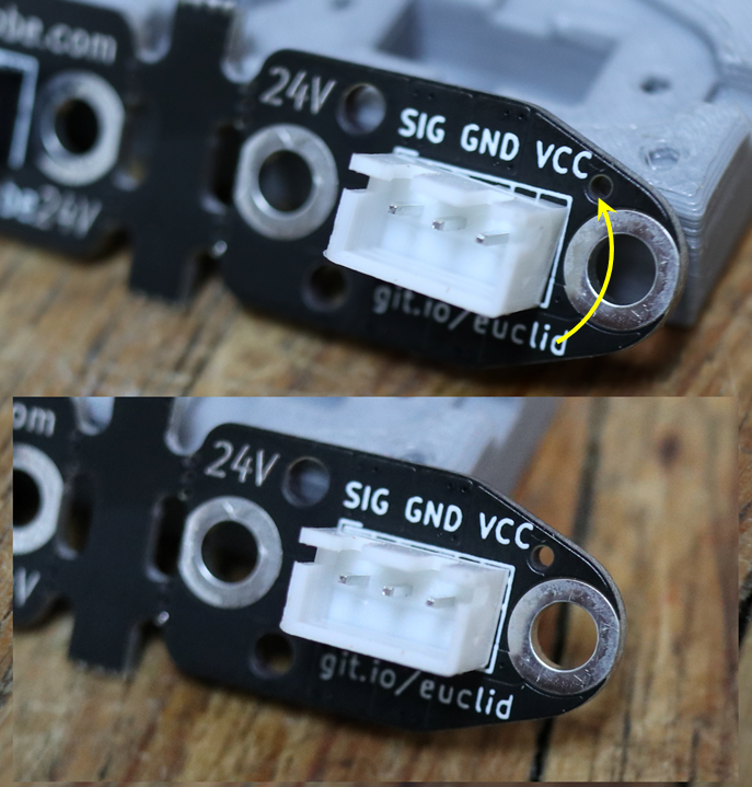
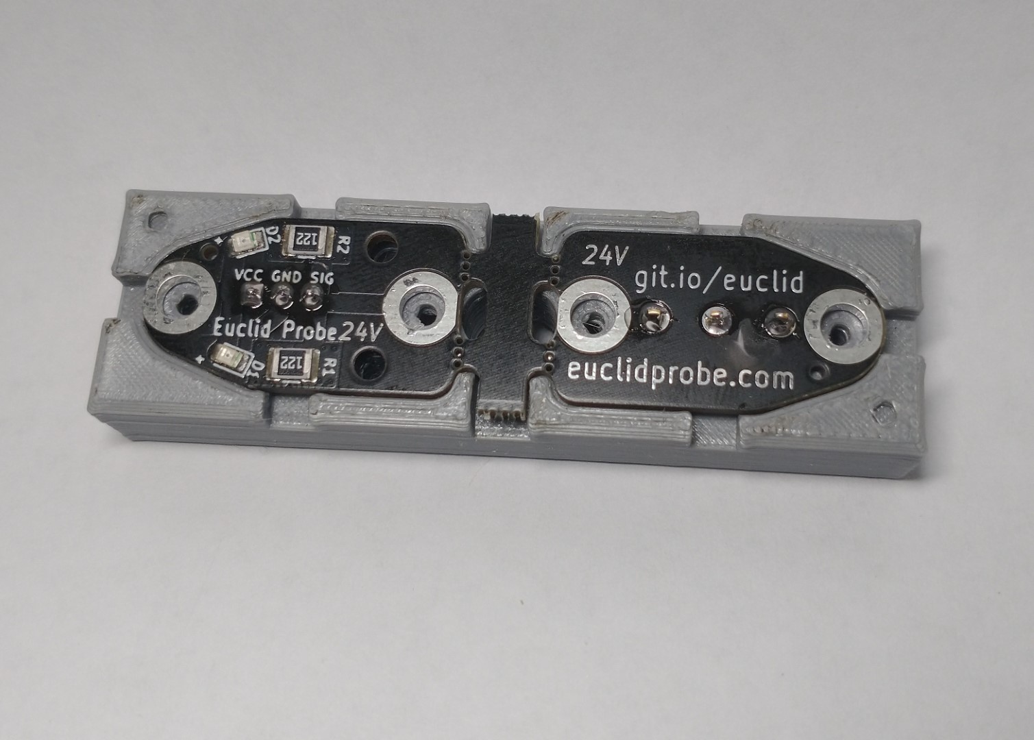
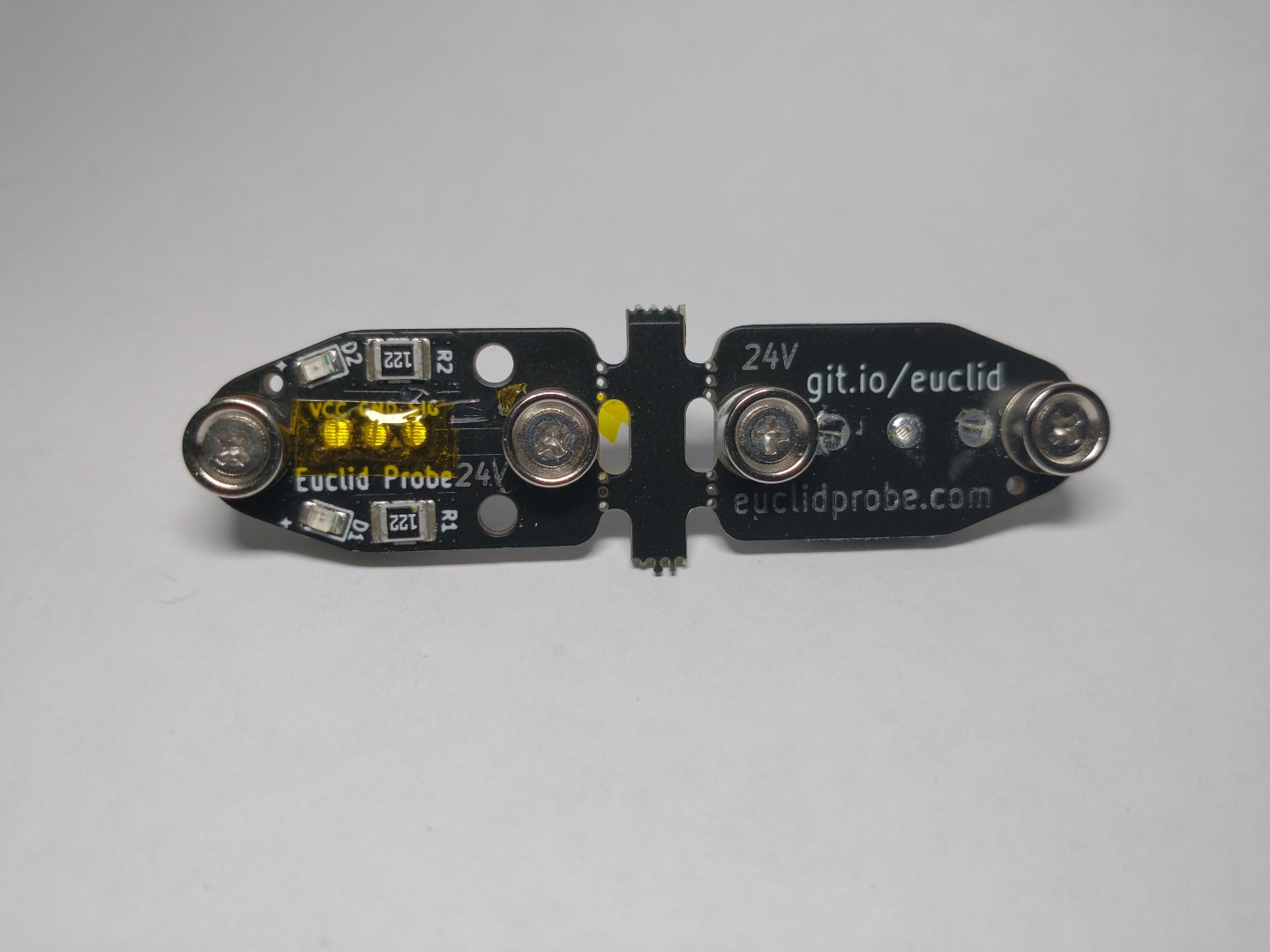
Install the wiring connector to upper tool board. This PCB has the outline of the JST-XH socket header printed on the backside and has the surface mounted components installed to the front side.
Install the connector from the backside of the board so that all the thru-hole soldering will occur on the front side. The socket header may be interchanged with header pins to use Dupont style wiring connector.
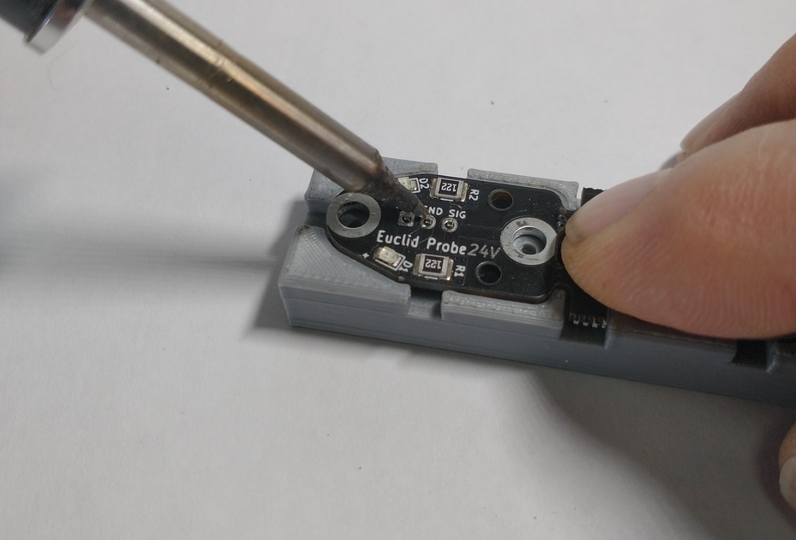
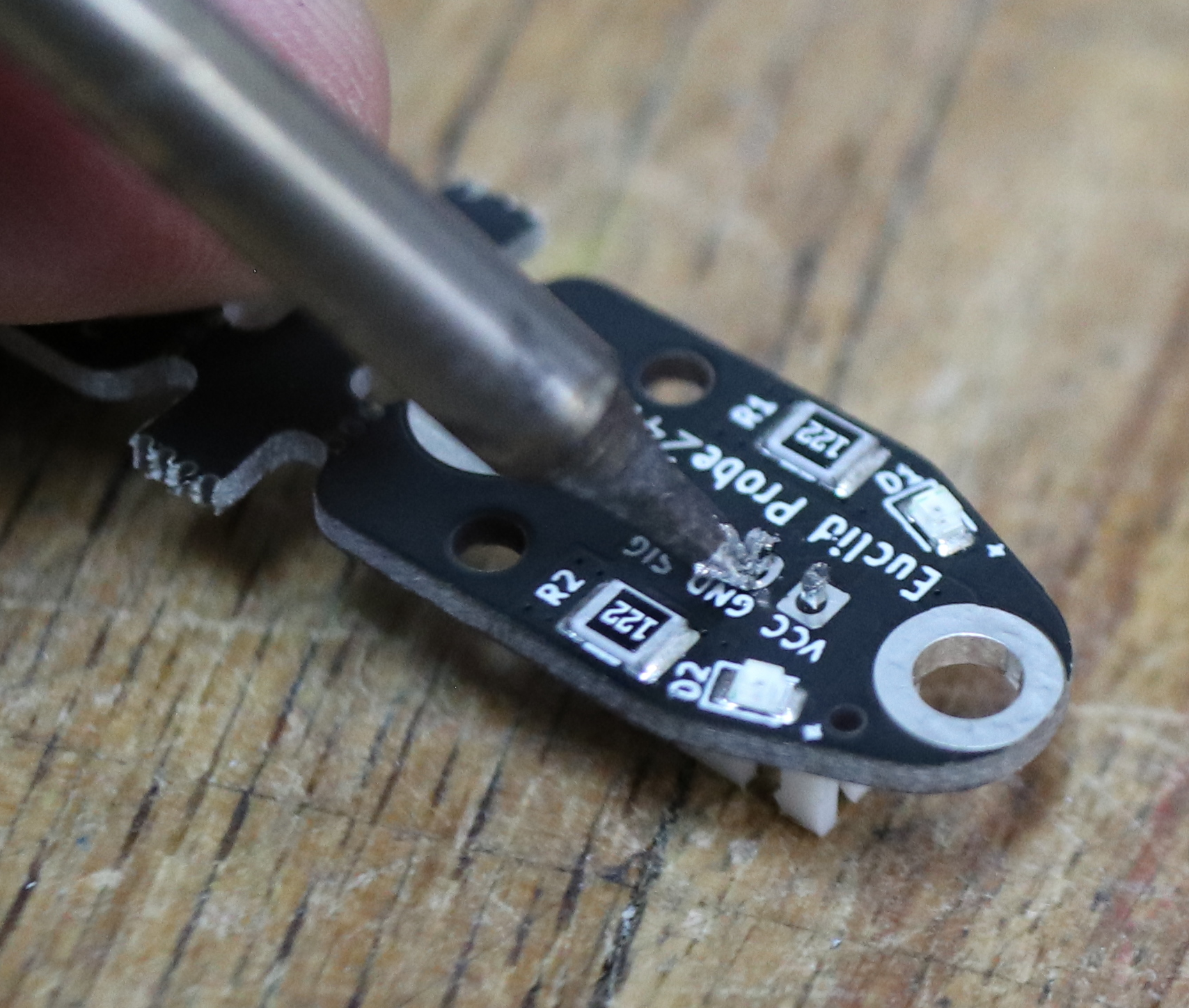
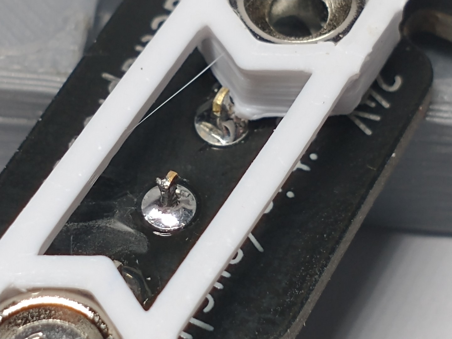
Install the switch to the probe board with the footprint labeled SW1. Install the switch from the backside. Note the pin labeling on the PCB silk screen printing and align the plunger fore or aft to suit.
It is important to fully seat the switch against the PCB when soldering. This eliminates any potential movement of the switch due to bending of the exposed pins, maintaining the best possible probe accuracy.
Check the alignments of both the header and switch. Adjust as needed and solder the remaining pins of the switch and connector to the PCB boards.
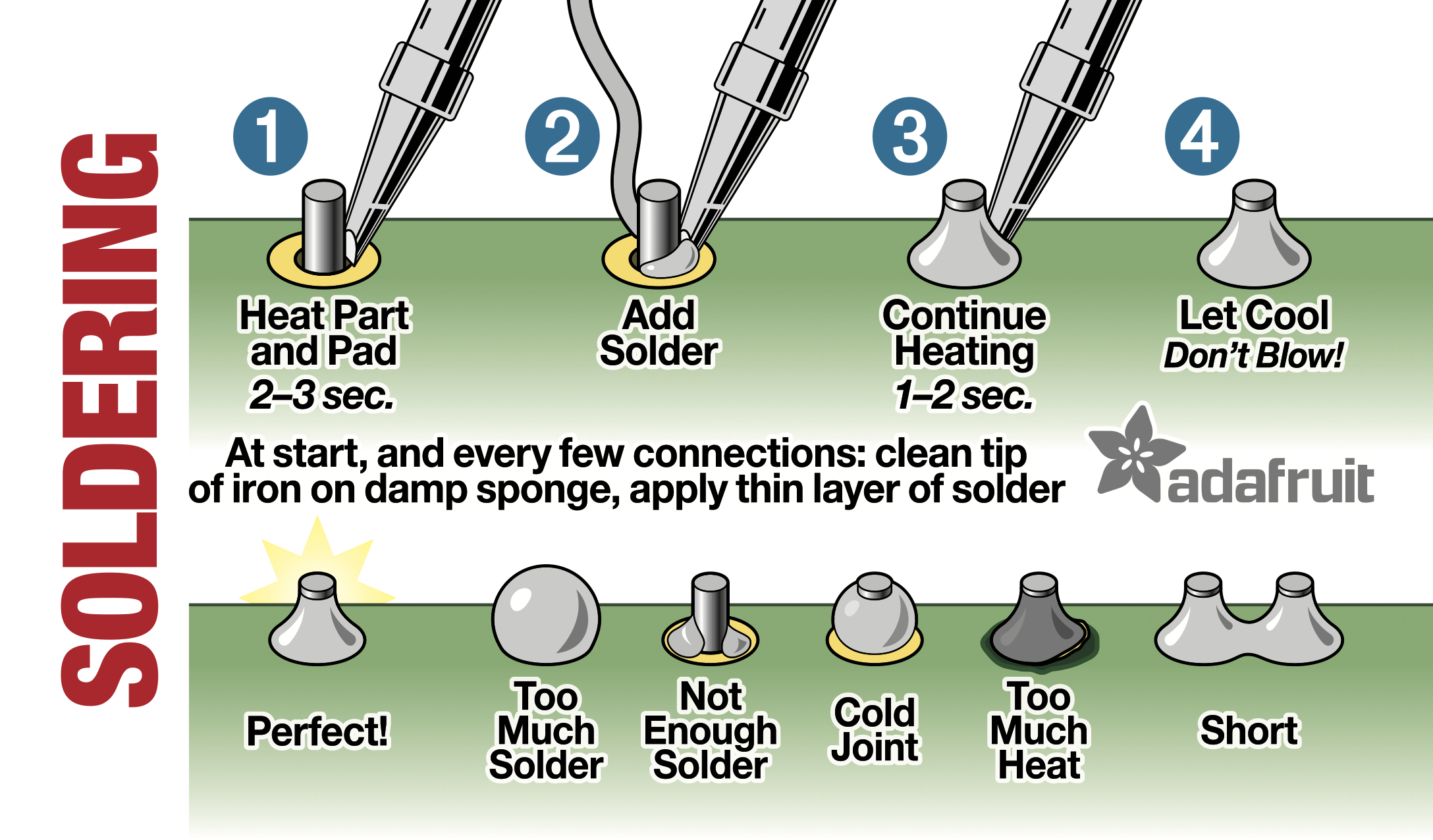
Soldering Tips
Soldering is an essential skill to have. Good tutorials exist online. Here is an example-
adafruit Soldering 101
Good joint? Bad Joint?
|
|
|
|
|
|
|
|
After soldering clip the excess length of the solder pins.
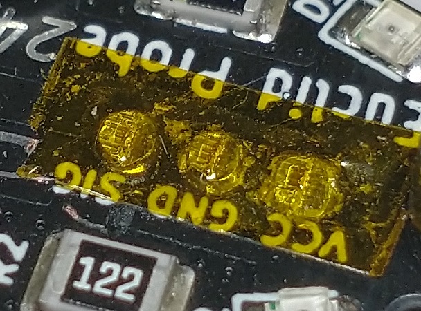
It is suggested to insulate the exposed terminals of the top PCB by:
- painting clear nail polish or model builder’s enamel
- placing a piece of Kapton tape (not included) over the exposed pins
- a small piece of blue tape
- a small piece of electrical tape
- ordinary Scotch tape is good to about 100C if nothing else is available.
|
|
Step 3 – Magnet Installation:
In the kit there are:
- 4, M2x0.4 by 5mm long screws
- 4 countersunk magnets
- 4 M2 SMD nuts
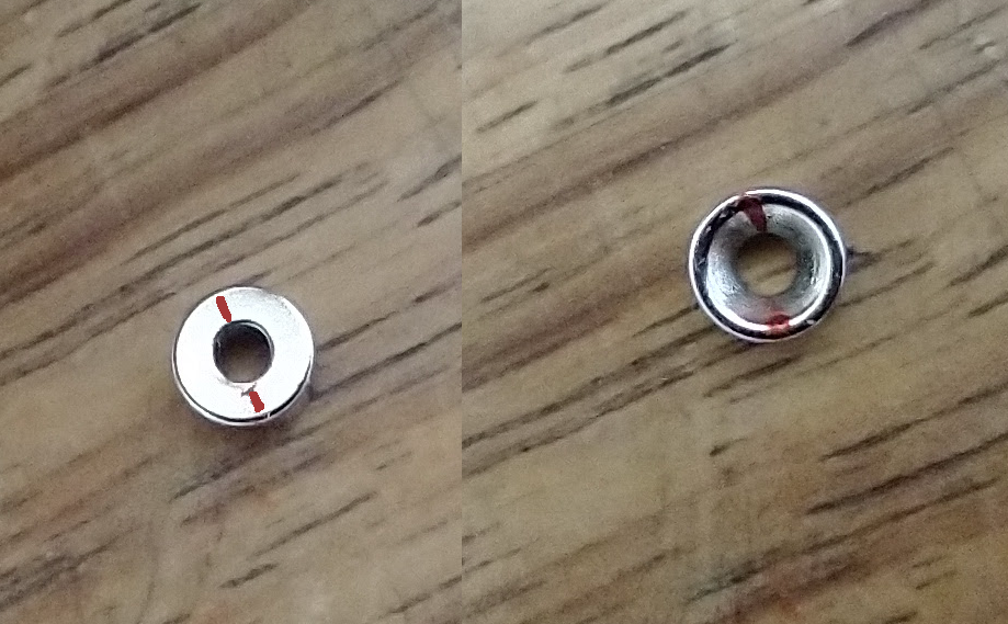
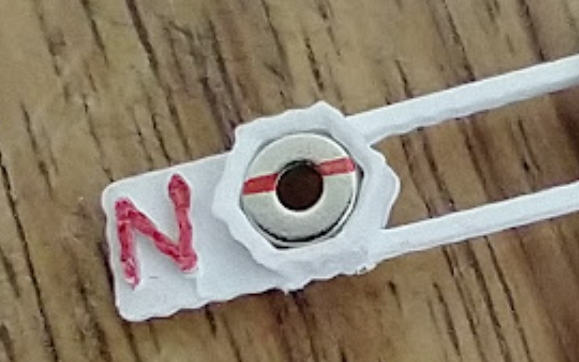
As of May 2022, the North polarity is now marked on the magnets. Hopefully this will make installation and verification easier.
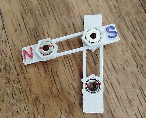
The suggested orientation of the magnets is such that the probe will only couple in one specific orientation by opposing the magnet’s polarities. The magnets area ideally orientated so that their poles alternate fore and aft on the board.
With the PBC boards attached the polarized tabs of the holders would be in the following patterns-
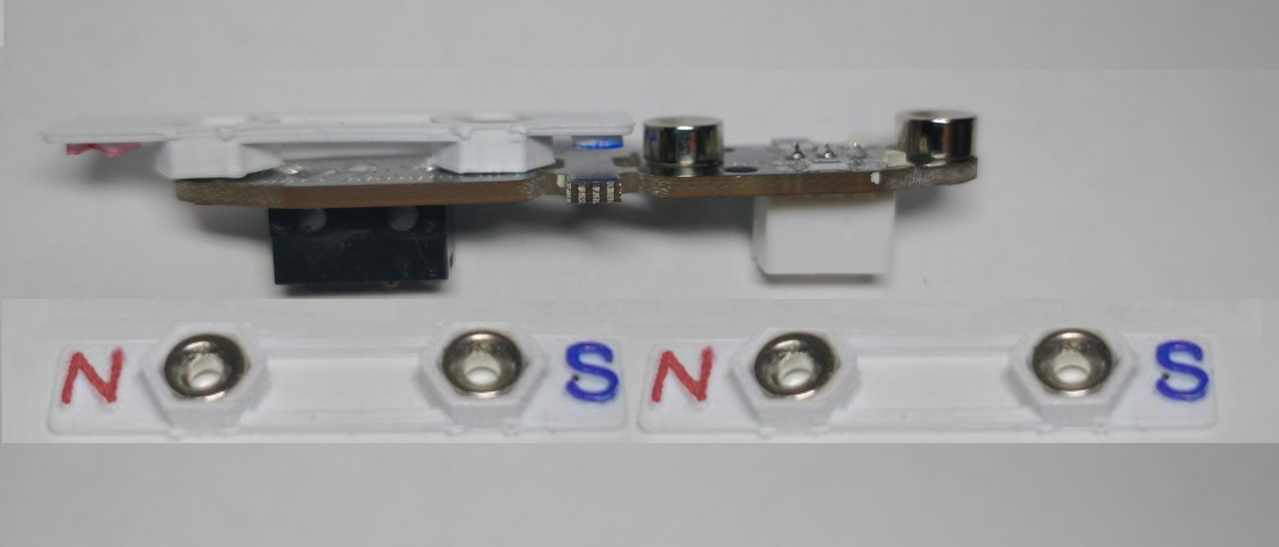
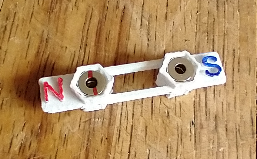
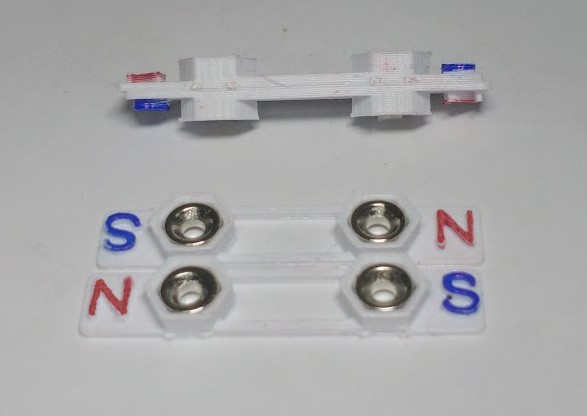
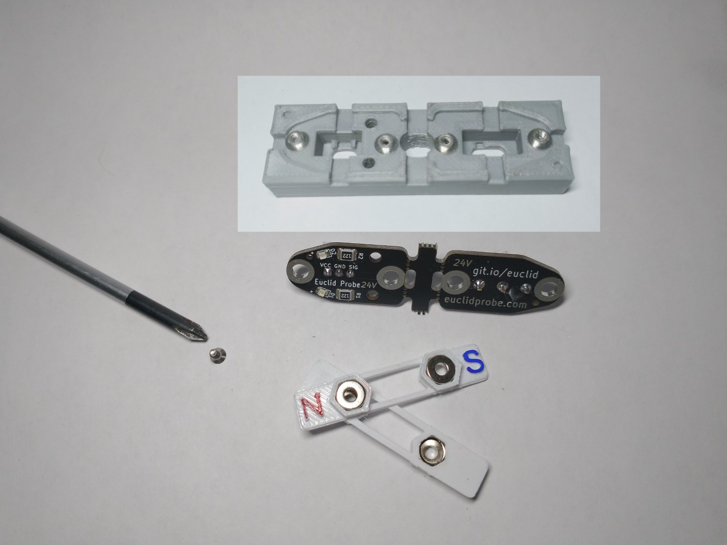
The photo below shows how we package the magnets in their holders with their polarities and countersinks already opposed. (The magnets are prevented from pushing out the flat back side of the holder). We identify the polarities with letters and color codes to aid in installation. The holders also space the magnets the proper distance apart for installation.
The intent is that the user swivels the holders apart and then inserts the M2 screws thru the countersunk magnet to install.
The magnets should easily eject from their holders- the direction of magnet ejection is opposite of their insertion.
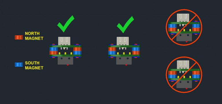
To reduce the likelihood of the probe randomly exiting the dock, the goal is that the leading magnet’s polarity is the same as the first. Since these two magnets are of the same polarity, they are repulsed, pushing the probe deeper into the dock and allowing the tool to pass over.
When the tool aligns the magnets properly, the probe will be lifted in the dock and couple with the tool.
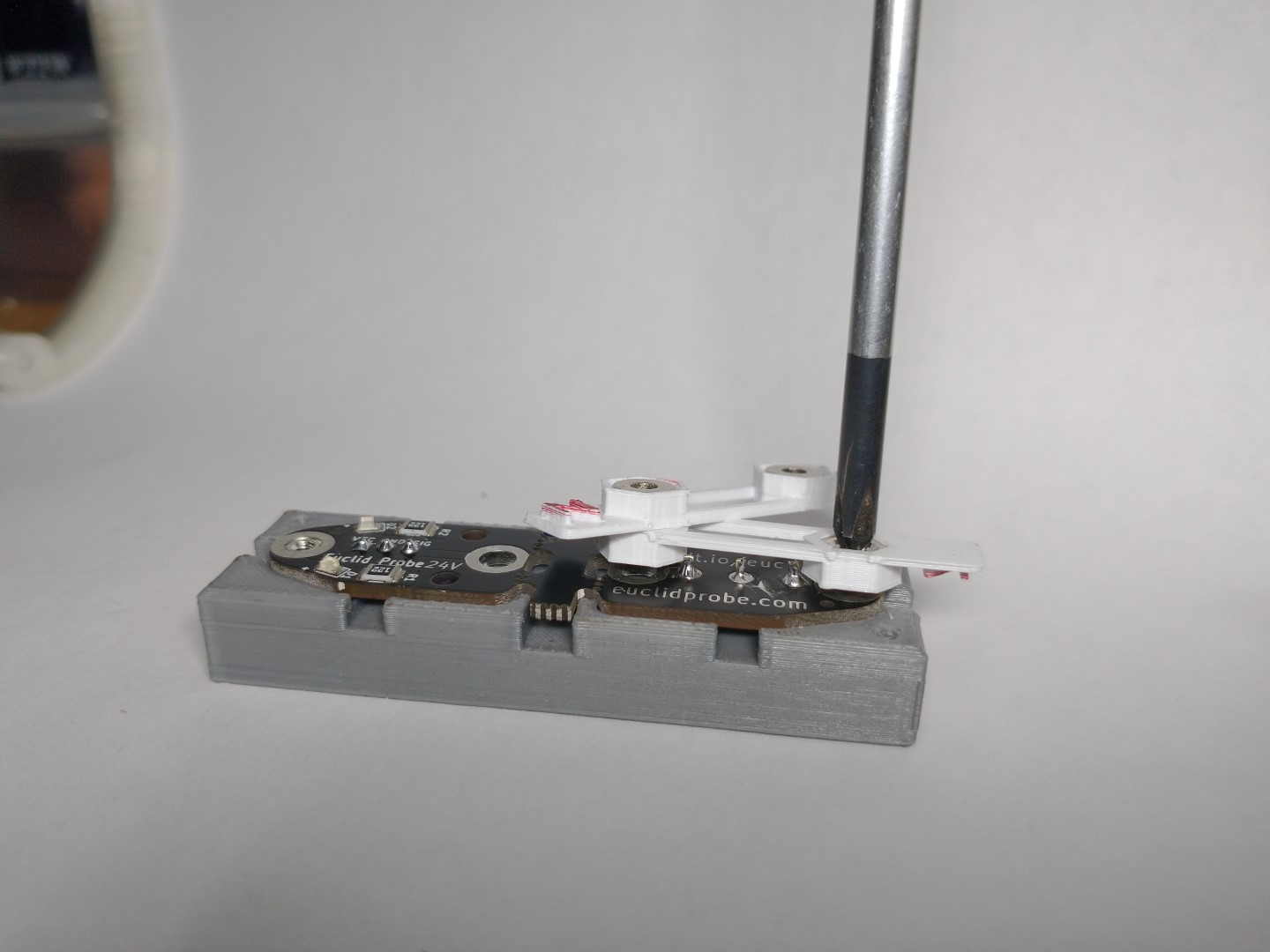
The solder jig aids in this installation step as well- place the SMD nuts on the jig and place the PCB on back top. You will then be able to put the swiveled magnet holders on top and screws through to attach.
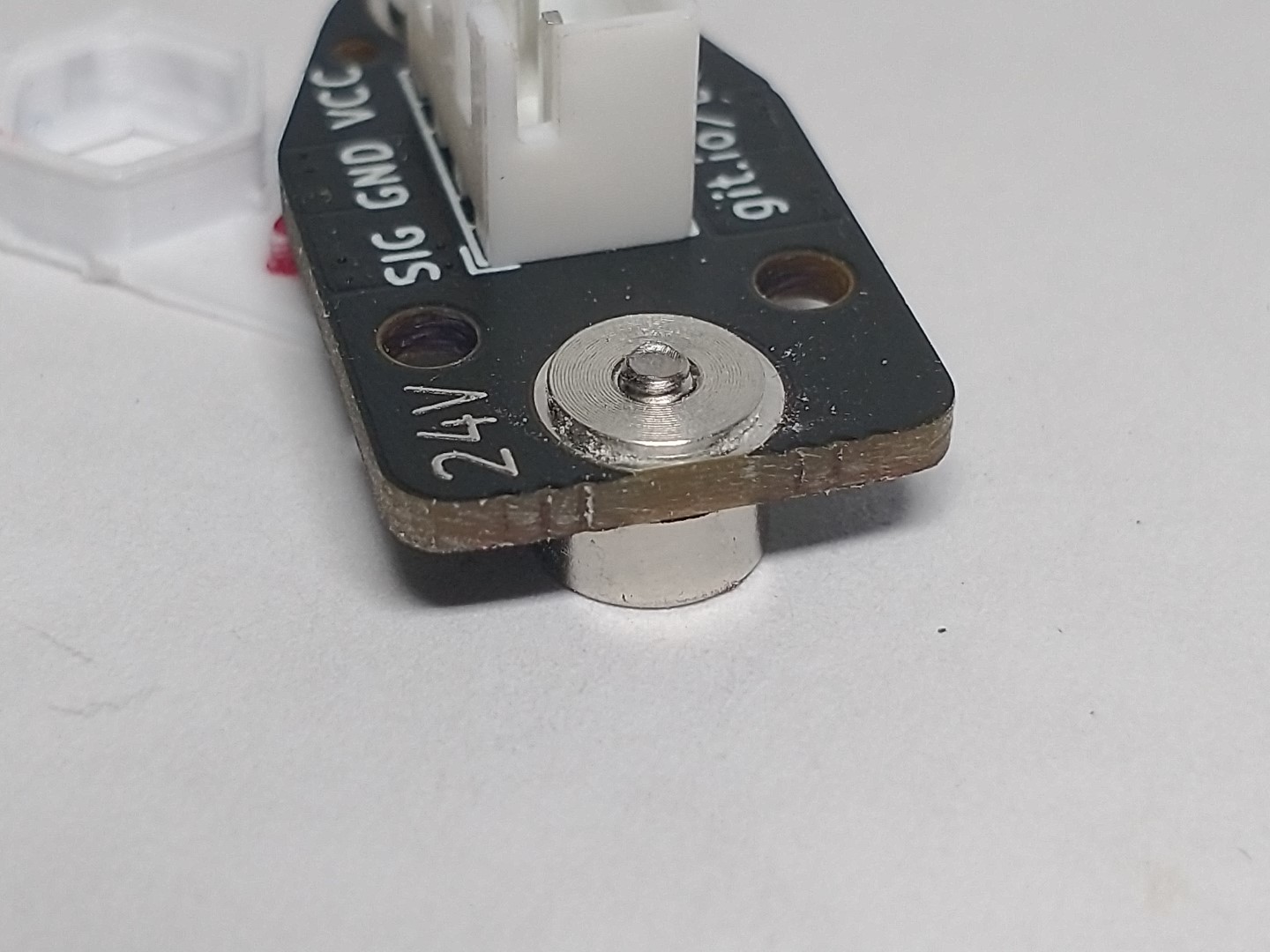
If not using the jig, place the shoulder of one of the SMD nuts into one of the holes of the PCB from the same side that the switch was installed from. Push the nut fully into the hole and screw the magnet into the nut.
The SMD nut is shallower than the PCB thickness and tightening the screw will cause the magnet to bear against the plated hole, creating the electrical connection. The magnet should now be protruding on the opposite side of the PCB board from the switch.
|
|
| Insert the SMD nuts in the jig. Separate the magnet pairs by swiveling. |
Insert screw through countersunk magnet into trapped SMD nut under PCB board. Tighten snug tight. |
|
|
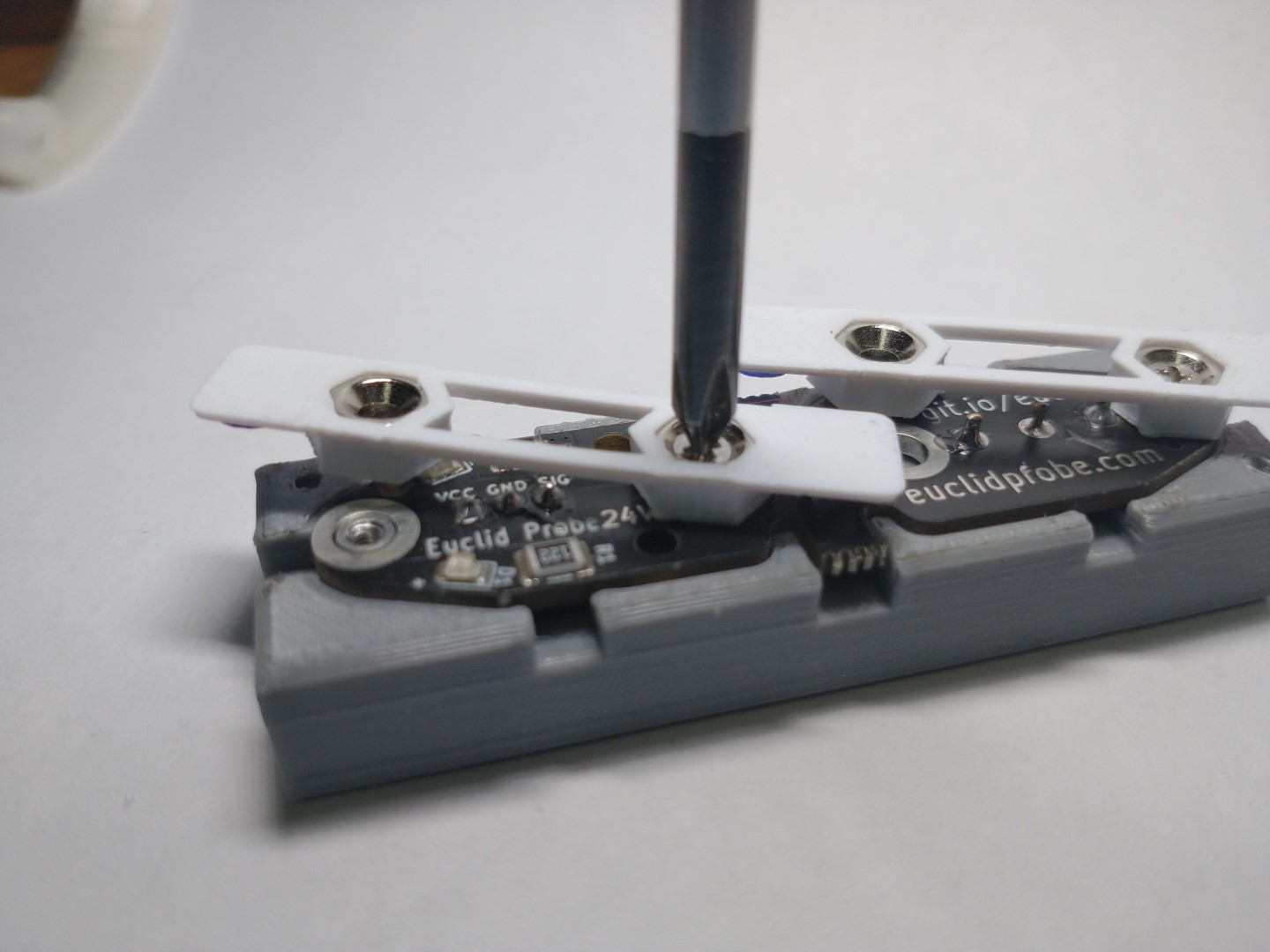
| Separate magnet holders and install magnet of opposite polarity to corresponding hole. Tighten snug tight. |
CAUTION: interference will occur if solder pins are un-clippped! |
|
|
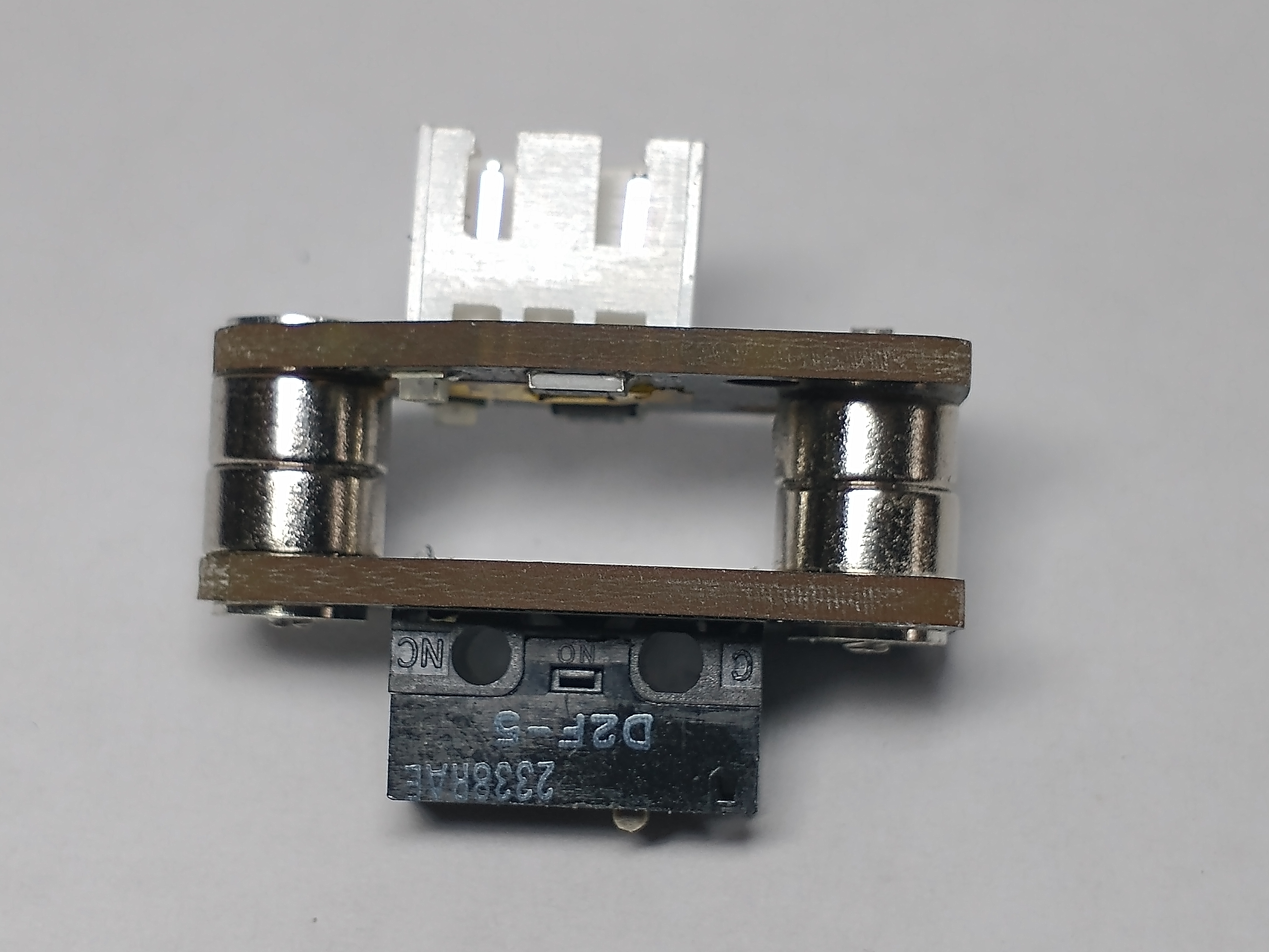
| Magnet holder prior to removal with screws snug tight. | Completed assembly! |
Install the remaining magnets and SMD nuts similarly into the open holes of the Probe Board and Tool Board. There might be an interference on the inside edges of the holder and the protruding pins- carefully eject the magnet and tighten the M2 screw.
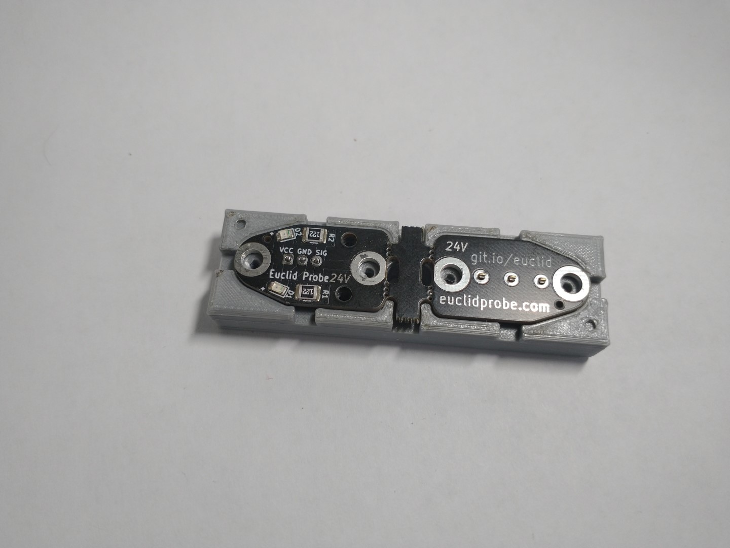
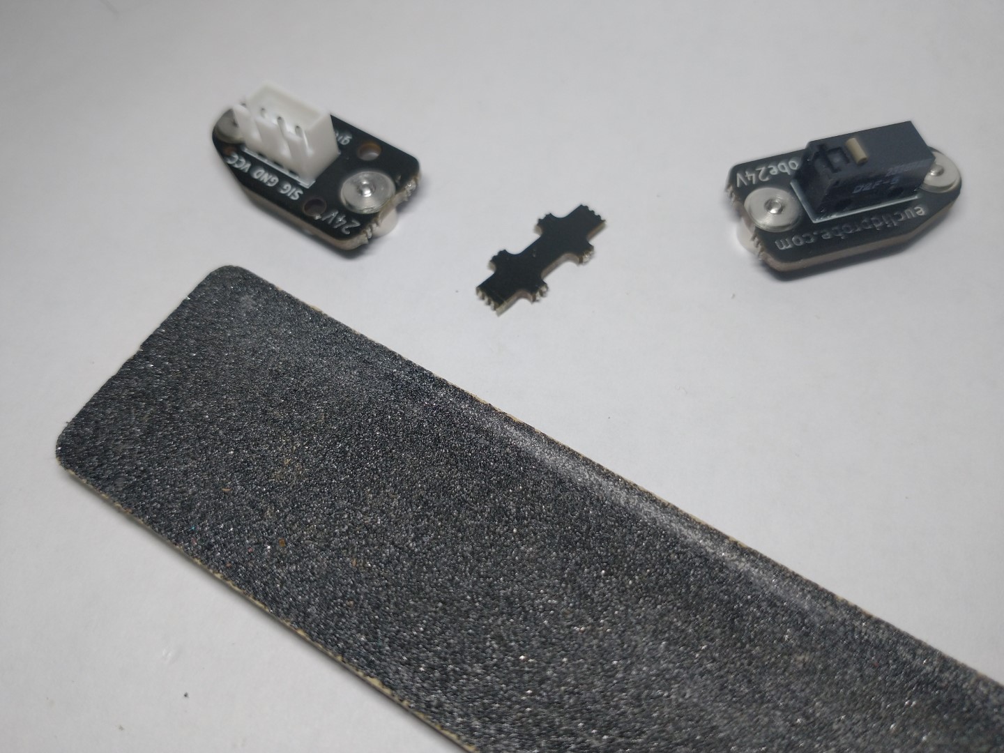
Step 4 - Separate the Boards
Separate the two boards from the PCB rail that joins them by flexing so that they crack between the mousebites holes drilled in the PCBs. If the rail remains attached to one of the boards, it can be carefully removed with flush cutters.
Use a file or nailfile / sandpaper to dress the rear edges of the toolboard. This is the most common offender if the board does not fit into recessed mounts.
|
|
| Separate PCB's from rail. | Clean up mousebites with file or nailfile. |
Step 5 – Magnet alignment check:
Place the two boards together and verify that the mating faces are drawn together.
If they are not, swapping the magnets ether top/bottom on one side, or end for end on one board usually corrects the misalignment.
Grasp the pair of coupled boards between your thumbs and forefingers and try to rock them side to side. If any of the magnet faces are not coplanar, you might feel or hear a slight clicking.
If you believe that this is present, try to identify the pair that is suspect, loosen the fixing screw on one of the magnets, rotate it slightly and re-tighten. This usually takes care of the problem.
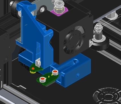
Step 6 - Attach to Mount:
Using the provided M2.5 self-tapping screws, or mounting system of your choice, attach the toolbaord PCB to the mount.
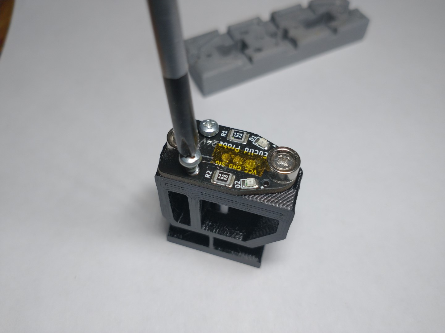
|
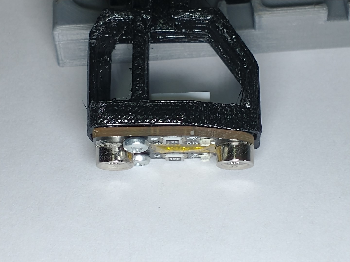
|