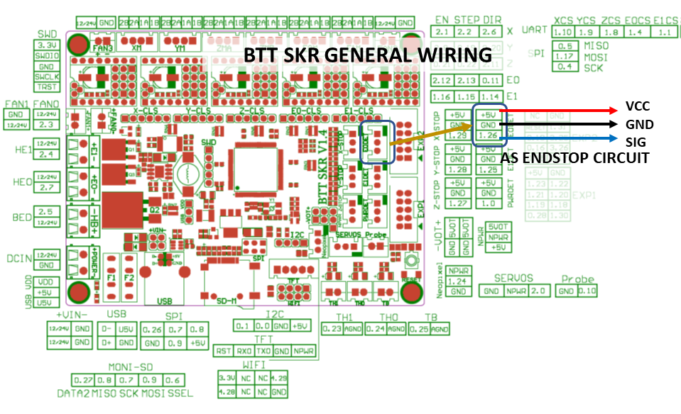
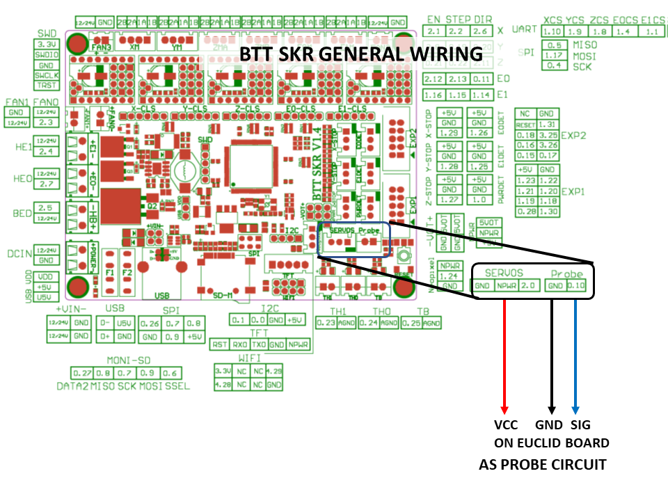
SKR Controller Commissioning
SKR series mainboards can use either the standard 5V or 24V Euclid models. Wire Euclid Probe to any open endstop connector or the Probe connection sockets with some care.
|
| SKR 1.x Series Mainboard Wiring Diagram as Endstop |
|
| SKR 1.x Series Mainboard Wiring Diagram as Probe |
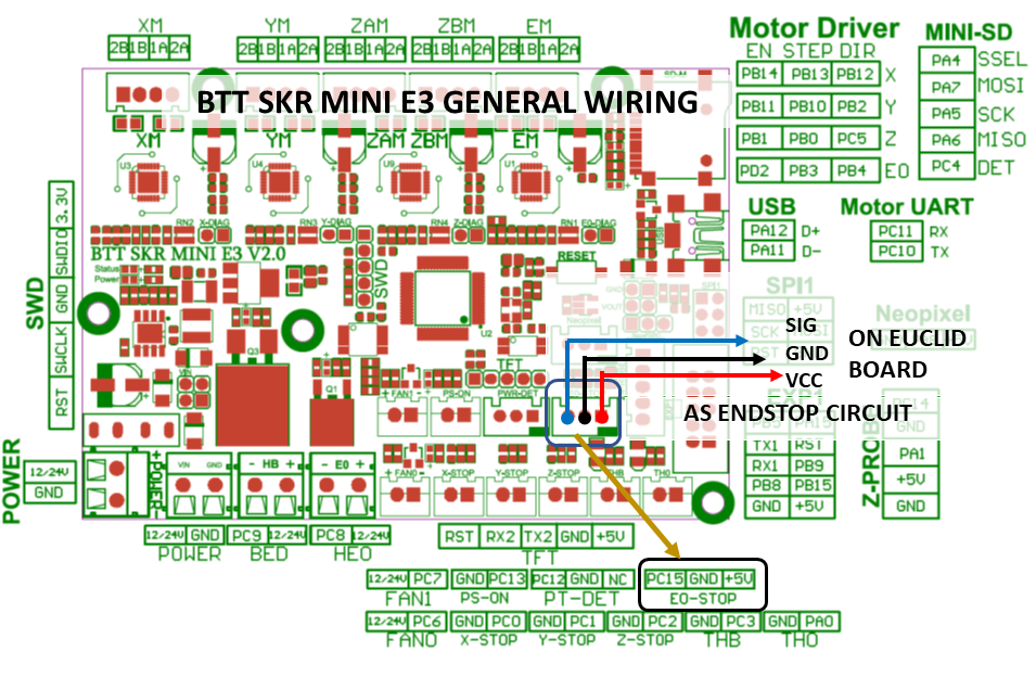
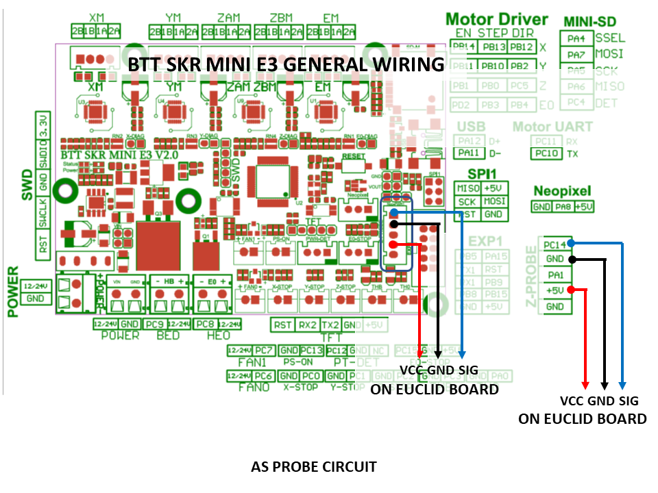
SKR Mini Controller Commissioning
SKR Mini series mainboards can use either the standard 5V or 24V Euclid models. Wire Euclid Probe to any open endstop connector or the Probe connection sockets with some care.
|
| SKR Mini Series Mainboard Wiring Diagram as Endstop |
|
| SKR Mini Series Mainboard Wiring Diagram as Probe |
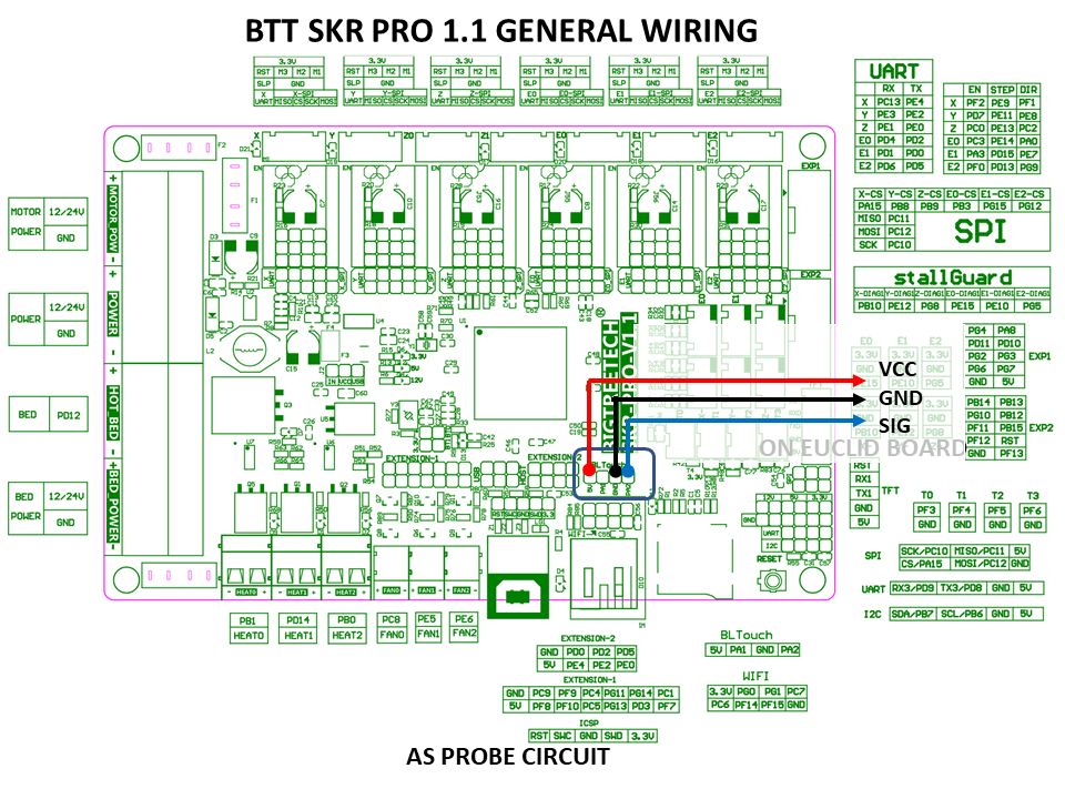
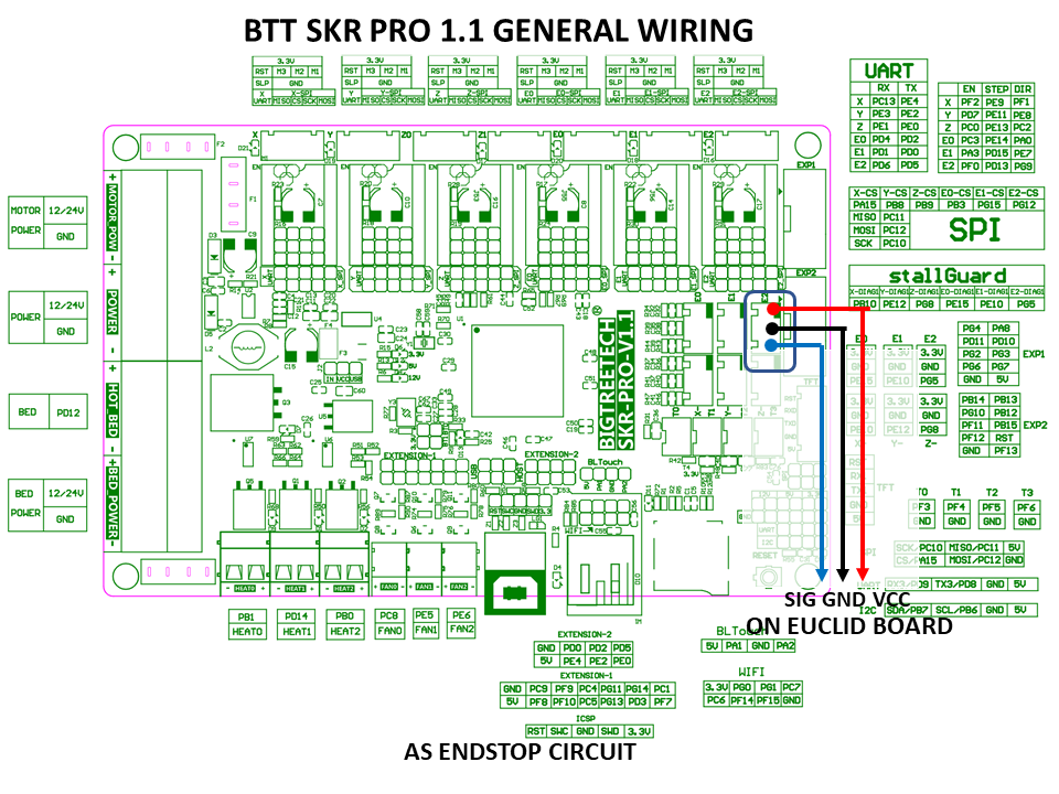
SKR Pro Controller Commissioning
SKR Pro mainboards can use either the standard 5V or 24V Euclid models. Wire Euclid Probe to any open endstop connector or the Probe connection sockets with care.
|
| SKR Pro Mainboard Wiring Diagram as Probe |
|
| SKR Pro Mainboard Wiring Diagram as Endstop |
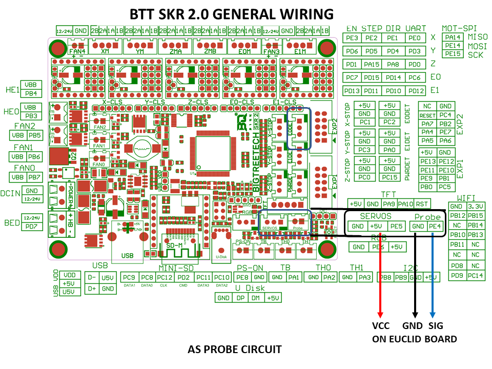
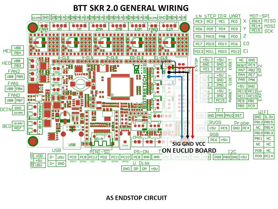
SKR 2.0 Controller Commissioning
SKR Pro mainboards can use either the standard 5V or 24V Euclid models. Wire Euclid Probe to any open endstop connector or the Probe connection sockets with care.
|
| SKR 2.0 Mainboard Wiring Diagram as Probe |
|
| SKR Pro Mainboard Wiring Diagram as Endstop |
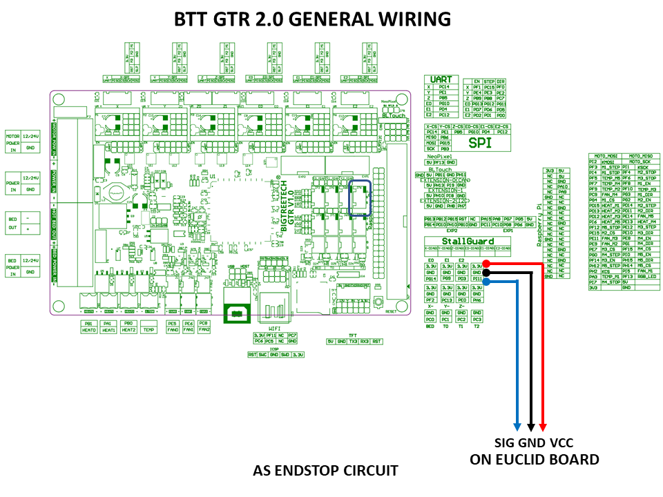
GTR Controller Commissioning
GTR mainboards can use either the standard 5V or 24V Euclid models. Wire Euclid Probe to any open endstop connector or the Probe connection sockets with care.
|
| GTR Mainboard Wiring Diagram as Endstop |
|
|
| GTR Mainboard Wiring Diagram as Probe |
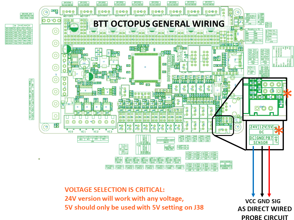
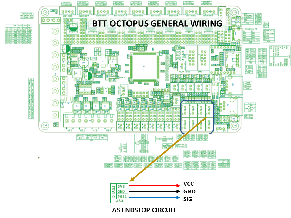
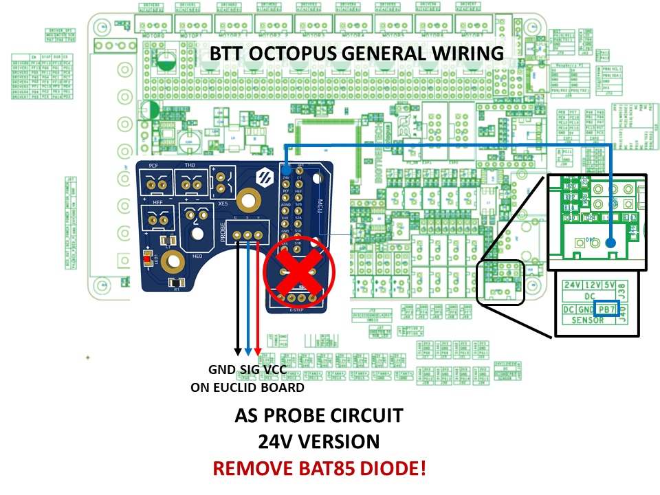
Octopus Commissioning
BTT Octopus has numerous revisions and only one is illustrated below currently. Users are encouraged to verify their deployment needs and coordinate with the schematic and documentation for their specific model.
Octopus can use either the standard 5V or 24V Euclid models whether Euclid Probe is going to be connected to an open endstop connector or 24V capable probe port.
If you are using klipper with the Octopus, there are some considerations to make- notably the use of the optocoupled probe port circuit and the BAT85 diode on a remote toolboard.
If Euclid Probe is to be wired to the Probe Port (pin PB7), you may need to set the probe pin LOW in order for the firmware to recognize the operation (~PB7). See Section 2.7 in the Octopus User Guide under Probe Port Wiring
If Euclid Probe is to be wired to the Endstop Port (pin PG11), you will need to use the BAT85 diode and set the probe pin HIGH in order for the firmware to recognize the operation (^PG11). See Section 2.7 in the Octopus User Guide under Probe Port Wiring
The topic we get the most inquiry about is the opto-coupled probe port on the Octopus. There are seemingly many variations on the optocoupled port. If the LED stays illuminated, then the optocoupler on the controller can not sink enough current for the LEDs to go out.
Our recommendation is to not use the Z_Probe port and use an endstop port instead.
|
| Octopus Pro Wiring Diagram with Euclid Probe on Probe Circuit |
|
| Octopus Pro Wiring Diagram with Euclid Probe on Endstop Circuit |
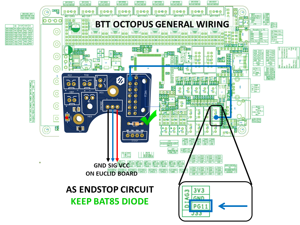
Octopus with Remote Toolboard Commissioning
BTT Octopus has numerous revisions and only the Pro is illustrated below currently. Users are encouraged to verify their deployment needs and coordinate with the schematic and documentation for their specific model.
Octopus can use either the standard 5V or 24V Euclid models whether Euclid Probe is going to be connected to an open endstop connector or 24V capable probe port.
|
| Octopus Pro Wiring Diagram with Euclid Probe connected to remote toolboard on an Endstop Circuit |
|
| Octopus Pro Wiring Diagram with Euclid Probe connected to remote toolboard on Probe Circuit |