A critical piece of Euclid Probe’s reliability is the captive dock for holding the probe when not in use.
Native probe mounts and docks were designed by, and have been extensively tested by Euclid’s designers on their own printers. Conversion and adapter mounts are also provided so users may retrofit their printer from other probes and devices to use Euclid Probe.
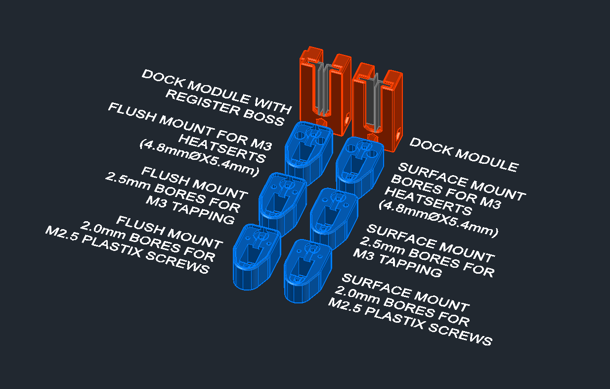
The modular building blocks provided are meant to be integrated into users own printer and other CNC machine designs.
Users are encouraged to review their dock locations and consider deployment/retract operations. The preferred locations for the dock tend to be behind the toolhead or in the opposite corners from the locations of endstop switches.
There is no single best place for retrofits. Homing macros may need to be adjusted to home one axis before another to avoid crashing into the dock, or flipping endstops to the opposite ends of their axis.
Some models are provided with Print-In-Place supports inserted by the designers. Typically the supports are thin features (~0.45mm in thickness) and offset from the supported surfaces (~ 0.25mm). Typically these print at single width extrusions and easily tear away. Some of these models are also provided without supports for those who prefer to model their own.
Recommend print settings for the mounts are either 0.2mm or 0.3mm layer heights, minimum of 3 perimeters, 20% infill of your choice, with either PC+ or ABS for higher heat resistance. Our test prints are made with a stock Creality Ender3-Pro with Superslicer using the default Ender3 profiles at with 0.28 Superdraft or 0.2 Normal settings using basic PLA filament (COEX Mystery PLA, Overture EcoPLA or Inland PLA spooless PLA+) .
Notice: The mounts provided with a recess for a PCB were modeled with a 0.2mm margin all around, intended to provide a close fit. Recent feedback suggests that this is too tight and in some cases an interference fit is occurring. While we research this, we recommend that users check their slicer settings, especially any for ‘internal hole compensation.’ In all cases, the recessed version is accompanied by a non-recessed version and we recommended to use those if the recessed versions are unsatisfactory.
Reference dimensions are noted in the illustrations where applicable for users to develop the probe offsets for their firmware.
Please use the 3D Previews of the .stls’ by clicking on the icons. If you haver disabled java support, the preview may not display correctly.