Locating Probe Offsets
The probe offset position relative to the nozzle is needed in all firmware configurations. The following image shows the probe location that used in some of the following firmware examples.
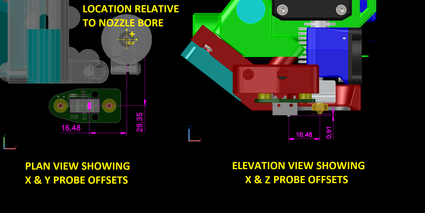
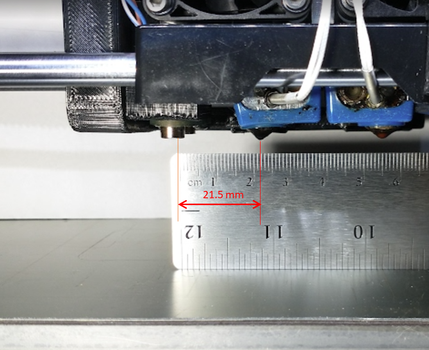
While having a CAD model is nice to reference, its not a requirement. A simple ruler, held on edge can be used to measure the centerline distances between the magnets and the nozzle.
Another good resource for determining the probe offsets is discussed on this Duet dozuki page.
Probe Z Offset
«««< HEAD To calibrate the Z probe trigger height, first verify that the probe stops when it senses the bed.
- Cancel any currently active mesh compensation.
- RRF use gcode
M561 - klipper use
BED_MESH_CLEAR
- RRF use gcode
- Home all.
- Jog the nozzle down until it is just touching the bed or just gripping a feeler gauge of known thickness or a sheet of paper (0.1mm). A Pokemon card is reputed to be 0.2mm in thickness. If the firmware doesn’t let you jog it down far enough, send M564 S0 to disable axis limits or use a force_override in klipper.
- Once you have the nozzle touching the bed or feeler gauge, send command
G92to tell the firmware that the head is at that position.- G92 Z0 if it just touching the bed
- G92 Z0.2 if using a 0.2mm feeler gauge
- G92 Z0.1 if using a piece of copy paper
- Deploy the probe
- M401
- Jog the head up by 15 to 20mm
- Probe the bed at the midpoint (X100, Y100 in this example)
G0 X100 Y100- RRF use
G30 S-1 - Marlin use
G30 - klipper use
PROBE
The nozzle will descend or the bed rise until the probe triggers and the Z height at which the probe stopped will be reported. You will likely need to manually move the bed to break contact with the probe.
To calibrate the Z probe trigger height, verify that probe probe stops when it senses the bed.
- RRF use
- Cancel any currently active mesh compensation.
- RRF use gcode
M561 - klipper use
BED_MESH_CLEAR
- RRF use gcode
- Deploy the probe (eg M401) and use the X and Y jog buttons to position the nozzle over the center of the bed.
- Jog the nozzle down until it is just touching the bed or just gripping a feeler gauge of known thickness or a sheet of paper. A Pokemon card is reported to be 0.2mm in thickness. If the firmware doesn’t let you jog it down far enough, send M564 S0 to disable axis limits.
- Once you have the nozzle touching the bed or feeler gauge, send command
G92to tell the firmware that the head is at that position.- G92 Z=0 if it just touching the bed
- G92 Z=0.2 if using a 0.2mm feeler gauge
- G92 Z=0.1 if using a piece of copy paper
- Jog the head up by 15 to 20mm
- Probe the bed
- RRF use
G30 S-1 - Marlin use ```G30``
- klipper use
PROBEThe nozzle will descend or the bed rise until the probe triggers and the Z height at which the probe stopped will be reported. You will likely need to manaully move the bed to break contact with the probe.gh-pages
G0 Z15
- RRF use
- Repeat from steps 5 two or three times to make sure that the trigger height is consistent.
The reported height is the Z probe height to use in your firmware.
RRF: refer to https://docs.duet3d.com/en/User_manual/Connecting_hardware/Z_probe_testing
klipper: refer to https://www.klipper3d.org/Probe_Calibrate.html
«««< HEAD
gh-pages
Probing Speeds
In general terms, we recommend singe probing speeds of 2mm/sec to start with.
If your firmware can perform 2-speed probing, 5mm/sec & 2mm/sec would be reasonable starting points.
We recommend that users perform their own repeatability tests to fine tune the speeds if faster speeds are desired.
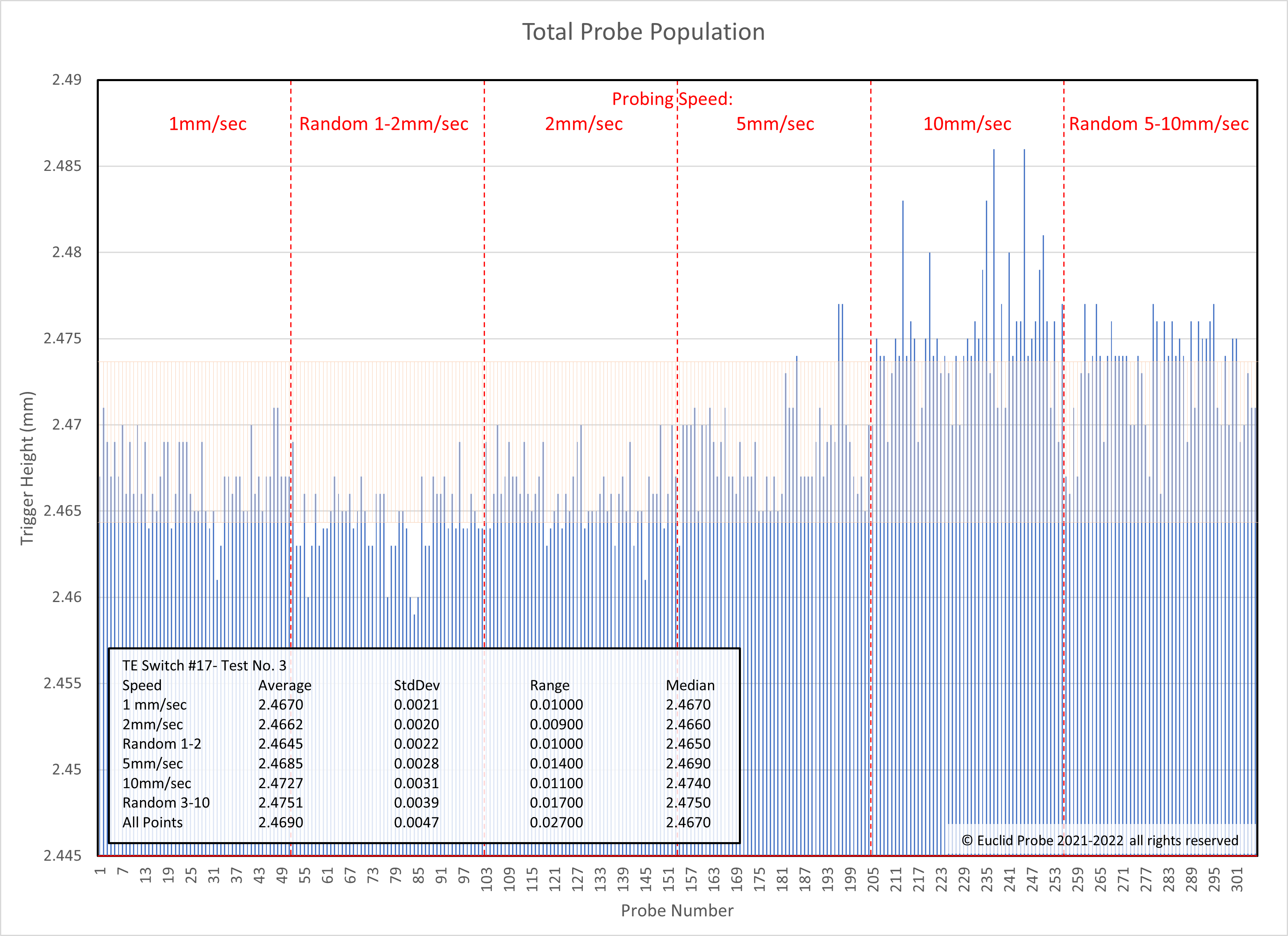
Here is the previous example of a single switch’s probing results performed at room temperature. Note the trends of the blue vertical bars showing the trigger point in the speed ranges noted at the top.
Also note the population of the probe points in relationship to the standard of deviation bars noted in orange. The standard of deviation bars are for the total population.
Click image to enlarge.