Determine the best orientation of the tool board and probe before assembly.
The orientation of the tool board does not necessarily have to match the orientation of the probe.
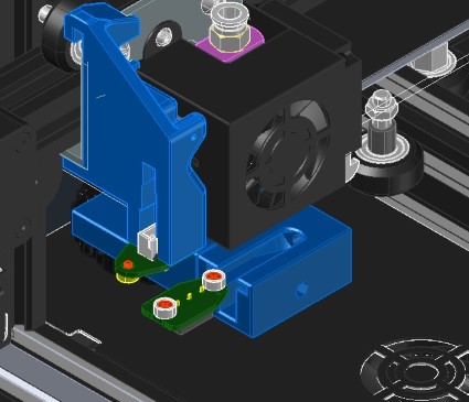
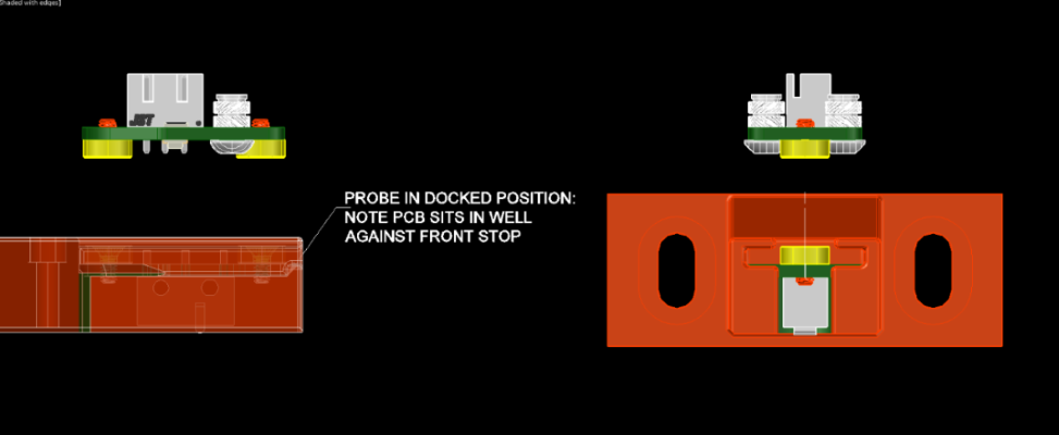
The probe is designed to enter the dock like an arrow, the wider section self-centering the PCB as it enters in case of any misalignment.
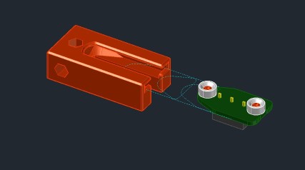
The ‘arrows’ can point in opposite ways. In fact, this is the orientation for an i3 style printer like an Ender3 or Wanhao i3, where the tool board motion points it to Xmin and the probe entering the Y-moving dock towards Xmax.
Locating the Probe Dock
Printer mounted docks are needed for automatic deployment and retraction. Depending on the firmware’s gcode programming capabilities, the dock can be either fixed frame or moving bed mounted.
The best place to put the dock is in a area that is outside of the printing boundary – the overrun area where things like purge buckets, nozzle wipers, tool docks, etc… live. This is the perfect location for Euclid’s dock.
If your printer does not have such an area, then an area roughly 15mm x 30mm in X & Y needs to be dedicated for the dock. It might sound worse than it is- even in the toughest adaptation, the max loss to print area was 4mm x 15mm.
The best advice we can offer is to look at the adaptations that are published in the .stls and CAD folder for inspiration.
The ideal location provides for both in and out motion of the probe into the dock, and as well a swiping action perpendicular to the dock to strip the probe from the toolboard.
Most often, this location ends up being in one of the back corners of any X-Y type machines.
On deltas style printers, the dock ideally mounts next to one of the rear towers.
Keep the dock and the dock mount as short as possible so it’s as stiff as possible.
Servo actuated docks & Linear stages
Docks attached to compound levers or bellcrank actuated mechanisms have performed better than direct attached docks to servo arms. These setups work, but we don’t currently have the resources to develop.
Here is an example of Jay_s’ servo setup on his Voron V0.1:
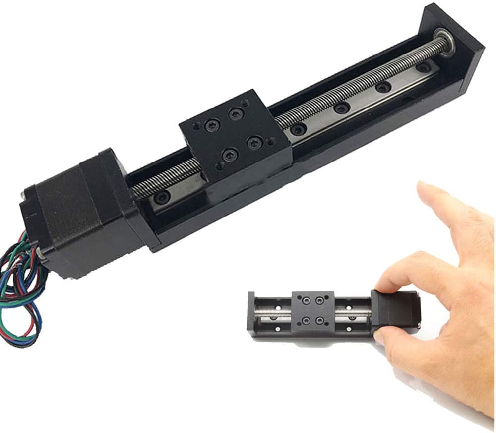
Here is an example of an inexpensive linear stage with 50mm of travel moving the dock into the print area and retracting it. IT uses a NEMA11 motor, leadscrew and a section of ball bearing rail to provide repeatable controlled motion.
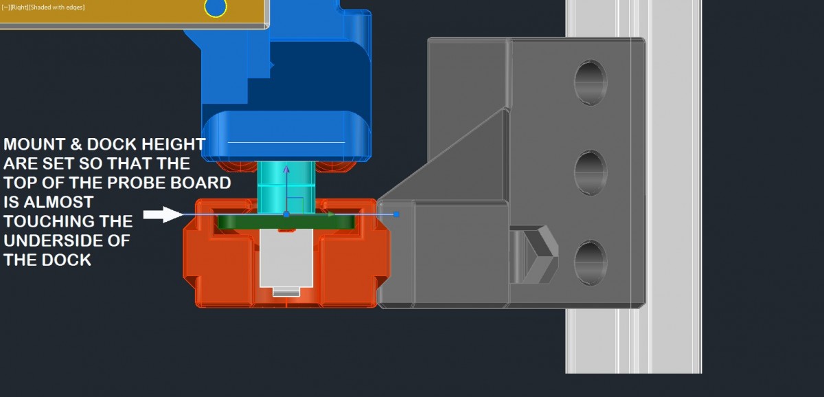
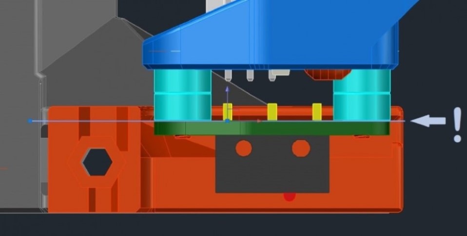
Setting the Probe Dock Height
The elevation of the dock is critical for consistent, problem free deployment and retraction.
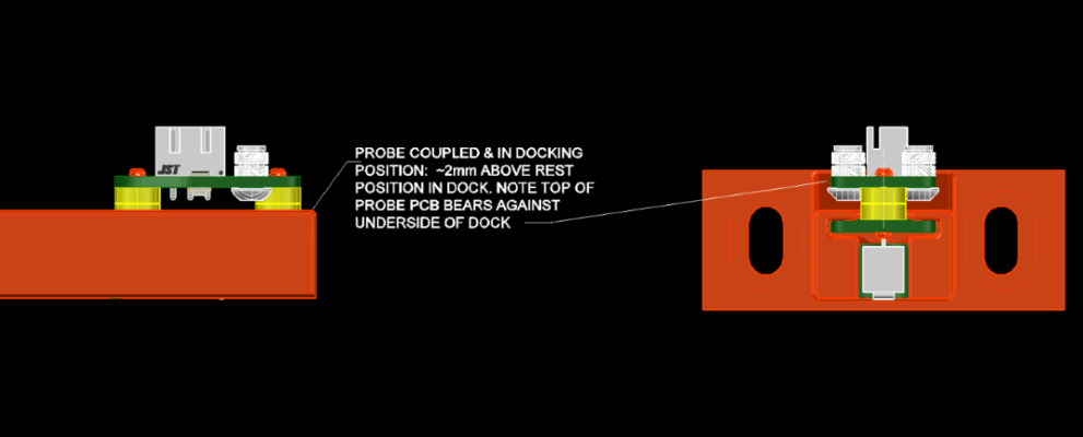
The ideal probe dock and toolboard designs allow for adjustments of the dock vertically so that when the probe is in the dock, it can meet the toolboard and be raised by the magnets to the proper elevation to clear the exit gate.
There are usually built in adjustment slots in the preconfigured docks for various printer models.
Printing the Dock
The usual probe dock is meant to be printed in an upright orientation with the print in place supports under the shoulder that the probe rests against when docked.
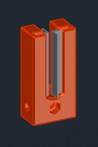
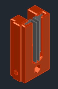
The version with a registration boss is provided to key into another part and to provide for some lateral adjustment. It is sized for an M3 screw as a draw bolt. The size of the boss is 6mm high by 1.5mm deep.
What are the holes for?
The vertical hole in the top of the dock was originally intended to provide a pocket for either a cylinder magnet or steel screw to provide something for the front magnet to attract to and retain the probe. Through testing, it was determined that neither is required.
However, this hole has been left in place to provide a space for a HALL effect sensor to be inserted and act as a visual indicator or part of a probe detection circuit. This will be covered in later sections.
 |
 |
|---|---|
| Modular Grafting Dock .stl | Modular Grafting Dock with Registration Boss .stl |
Community discussion and support is available as a subgroup to the CroXY Discord