Commisioning
The first step in commissioning Euclid Probe is deciding if the device will be wired as a Z-Probe or an endstop. Euclid Probe can be configured in most printer firmwares as both and endstop and as a probe.
Refer to your printers firmware documentation for determining the most ideal way for your configuration.
Wiring to other ports such as dedicated Z-probe or remote I/O ports are also possible.
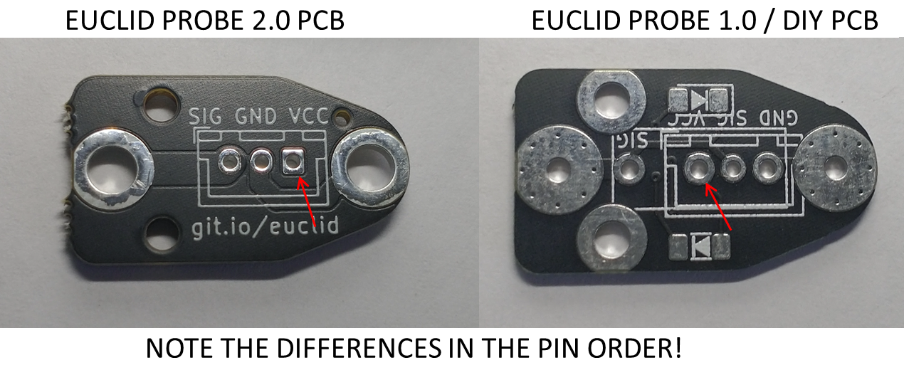
Note the Pin Order
There are differences in the pin order for the wiring socket holes between board versions. Version 2.0 of the PCB was made more consistent to the pinouts of production controllers.
Users are encouraged to verify the pin and wiring order for their particular printer.
5V & 24V Version Differences
Euclid Probe can be wired direct to a remote toolboard that provides 24V sensing voltage and used with a controller that has a 24V probe input. In this application, the 24V version is most appropriate. The 24V version is all voltage capable.
If your controller is not high voltage capable, the the standard 5V model is sufficient. This includes RAMPS based controllers, Duet2 and Duet3 hardware, most LPC and STM based controllers without high voltage inputs.
Basic Wiring: 2-wire mode
The Euclid Probe can be wired and function with as few as 2 wires connecting the SIG & GND pins on the toolboard to the controller. The LED’s will not illuminate in 2-wire mode.
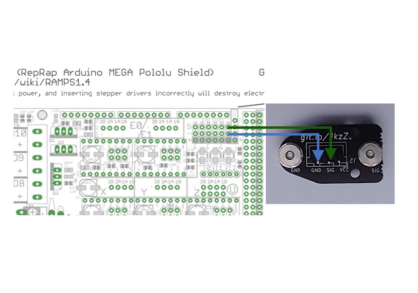
Using the appropriate wiring crimps and connector shells, terminate the wiring of your choice and connect the wiring loom to your controller.
Perform a function check with a multimeter or test light before final installation of Euclid Probe. With the probe and toolboard coupled, use the Continuity Function of your meter and check for continuity across the pins marked GND & SIG. If the circuit is complete, the probe was assembled and coupled correctly.
Intermediate wiring: LED operation, 3-wire mode
To illuminate the LED’s on the toolboard, a third wire must be connected to the VCC pin on the tool board. This wire should be connected to the logic voltage of he controller, the same way as with 3-wire endstops with LED’s.
Depressing the switch will cause the circuit to open and the LED’s to turn off.
The LED’s will blink off when the machine is probing the bed.
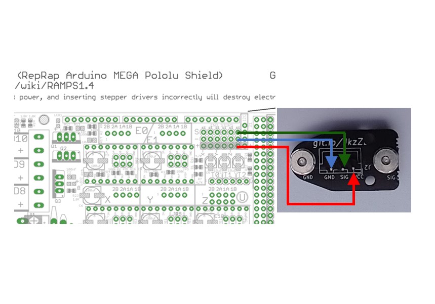
Early Euclid boards and current DIY boards have a connector pinout that is ordred GND-SIG-VCC. If a pre-terminated endstop cable is used to connect Euclid to the controller, two of the terminals will likely need to be re-pinned.
Current Euclid Probe kits have, and future DIY boards will have, the more conventional SIG-GND-VCC pin order and can be connected with a premade straight through endstop cable.
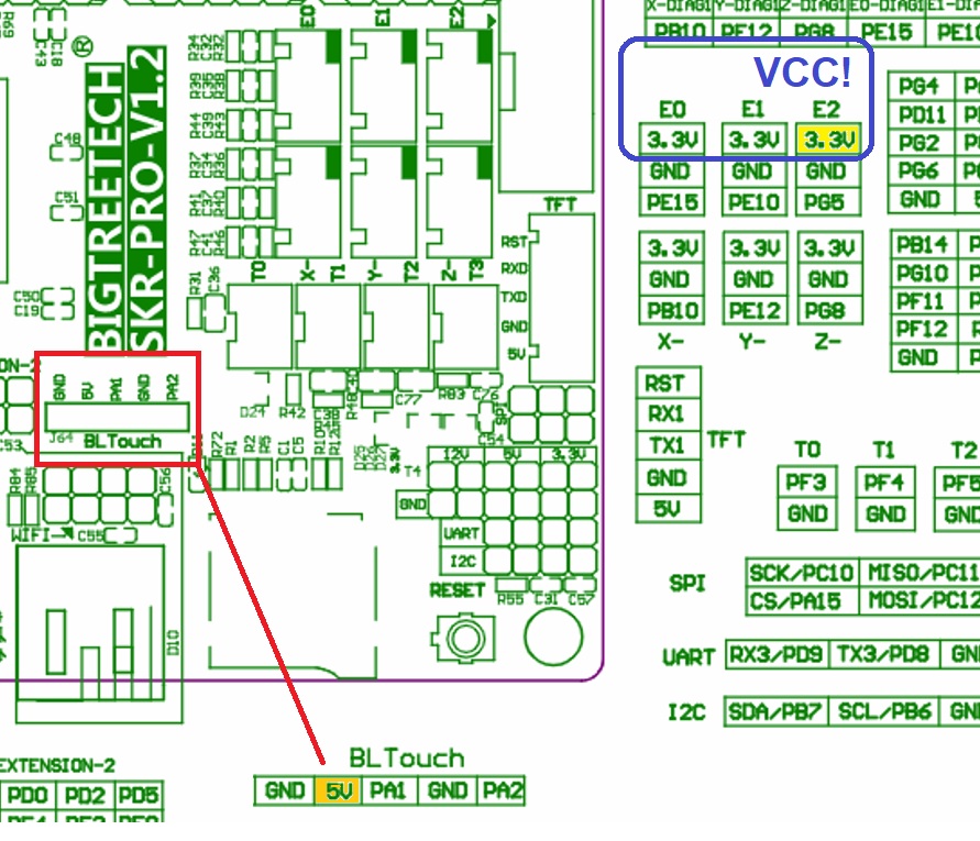
Replacing a BLTouch / CR Touch device
Some controllers have a dedicated 5-pin connecters for these devices. Two of these pins are dedicated to the SIG-GND function of the device as I/O and the other 3-pins are dedicated to the operation of the internal mechanical devices as servo devices.
The probe signal pin may or may not be 5V tolerant. It is recommended to verify your controller’s requirements and if in doubt, use an unused endstop connector instead.
Advanced Wiring
Wiring Euclid Probe to a remote toolboard requires coordination with the controller manual and related device schematics.
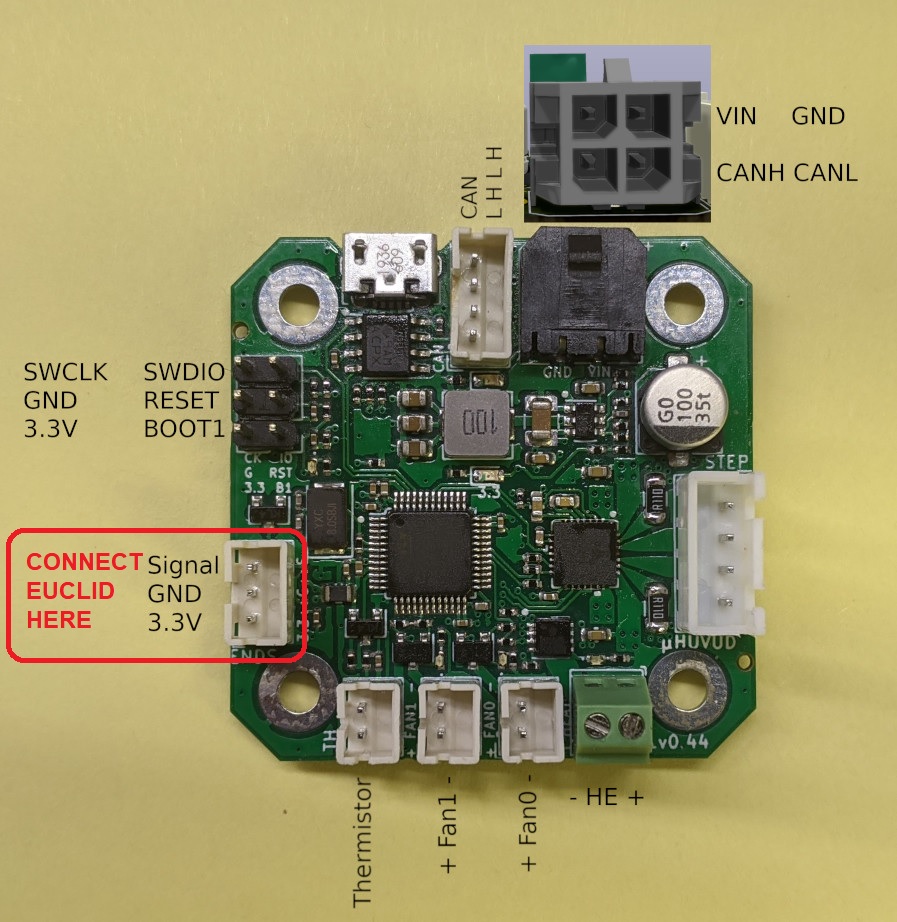
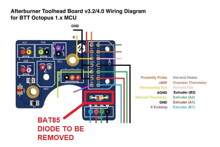
- Early high-voltage boards made use of a BAT85 diode which acted as a current limiter on the probe circuit.
- Some toolhead boards require removal of the remote BAT85 Diode for proper operation of optocouplers on the controller.
- CAN type controllers can provide 3.3V or 5v on their I/O ports.