Probe Accuracy Testing
Little to no application data was available for the types of switches used in Euclid Probe. Therefore, the engineers and designers who created Euclid Probe embarked on their own testing campaign to qualify the switches and the other components used in construction. This includes mechanical accuracy testing of the individual switches, the entire probe assembly, and actual probe deployment and probe docking cycles on our test printers.
To date, over 500,00 probe deploy-probe-retract cycles with a moving Z-axis dock have been performed. The only probe docking failures were due to operator error: not updating the probe Z-offset between sample changes.
The gathered data was compiled and analyzed to compare the performance between different switch manufactures and models. The overall results have been quite revealing- the usual suspects are not as accurate as they are purported to be, and the other brands and models often dismissed are actually quite accurate.
Repeatability’s often approach 0.001mm.
Here is an example of a single switch’s probing results performed at room temperature. Note the trends of the blue vertical bars showing the trigger point in the speed ranges noted at the top.
Also not the population of the probe points in relationship to the standard of deviation bars noted in orange. The standard of deviation bars are for the total population.
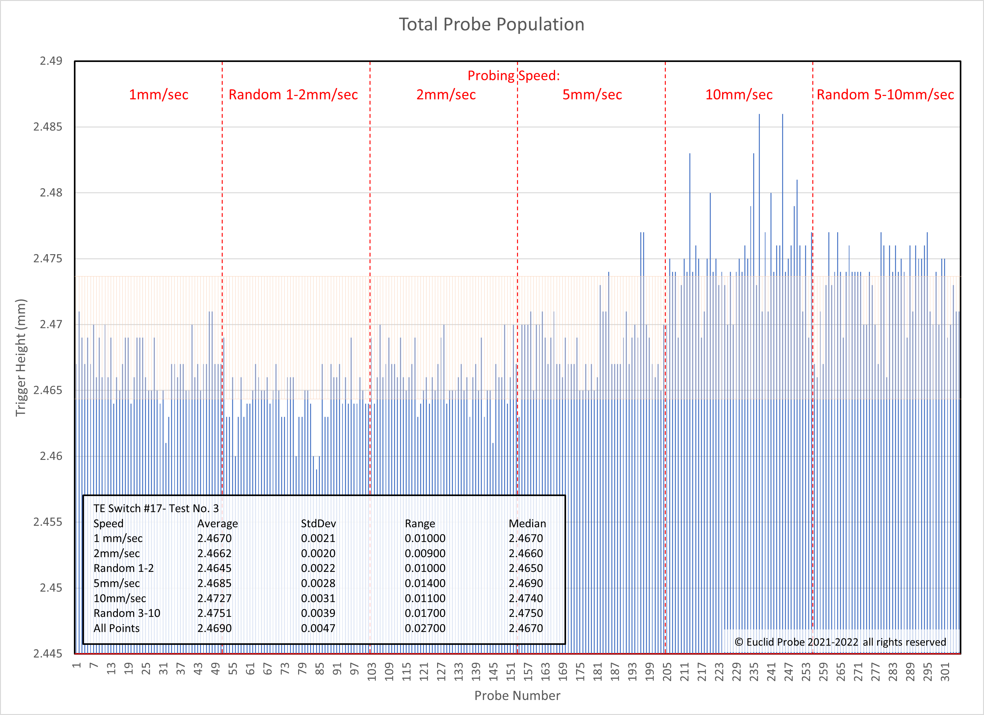
Click image to enlarge.
How accurate is Euclid Probe?
Generally speaking, an order of magnitude more accurate than the nearest competing devices or technologies.
The probing results will vary based on the firmware and mechanical system of the printer, but we have seen repeatabilities approaching 0.0005mm.
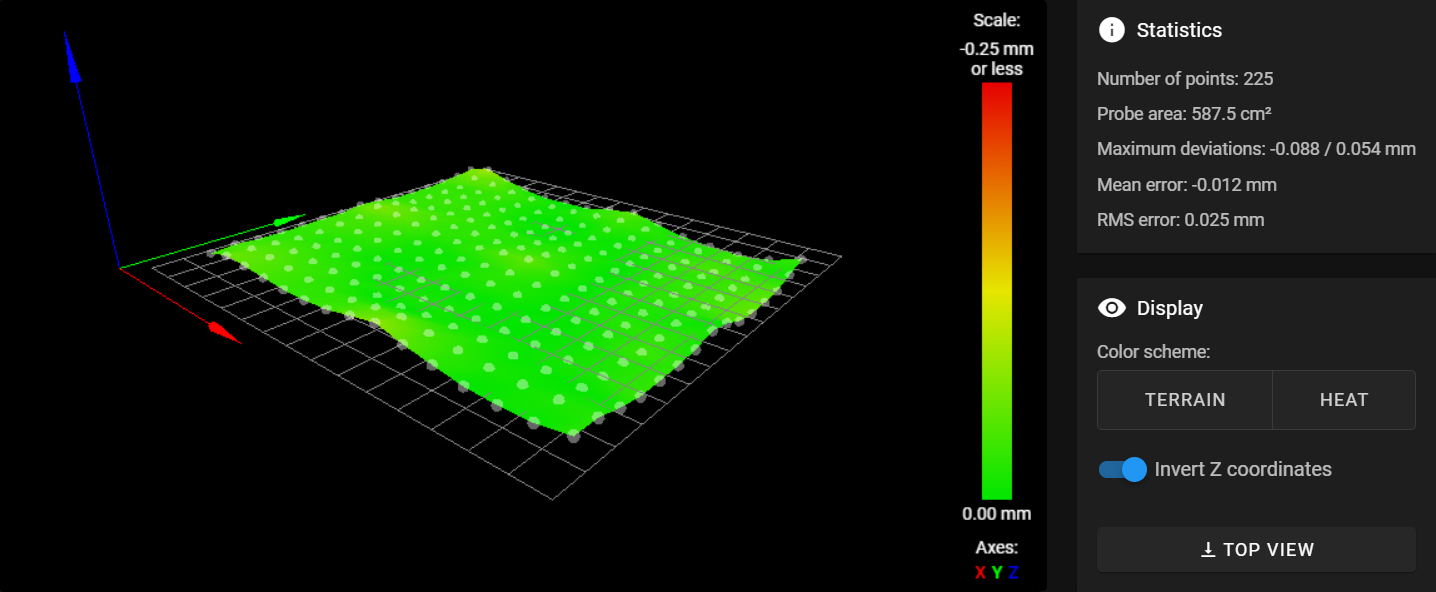
Below is a bed map submitted by a user who was convinced that Euclid Probe was being influenced by the bed magnets. Note that the Z variation is inverted (what is ‘low’ is actually being displayed ‘hi’).
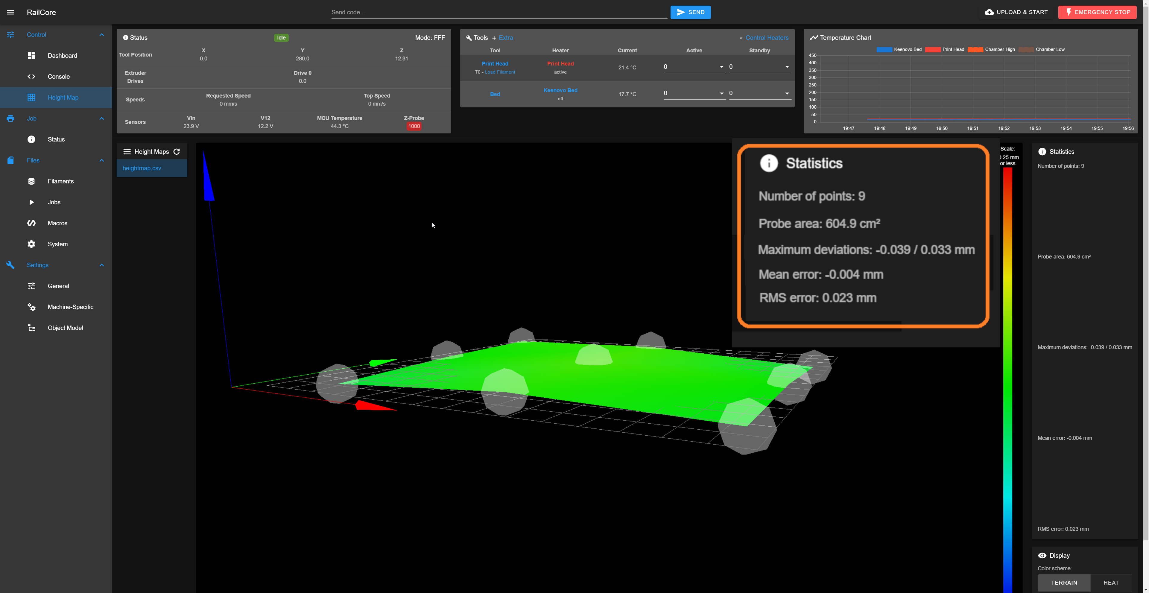
After some consulting with the user, we advised them to place paper shims over the magnets to determine if there was a hollow over the top of the magnet which would draw down the steel build plate. The results were that the steel build surface was truly being drawn into the hollow above the recessed magnets. The user the carefully shimmed each magnet with paper and cigarette rolling paper shims to level the bed. This was their result-
No, really its that good!
Here is actual output from a user who is using a Euclid Probe on a Railcore 300ZL printer- 2 iterations of their bed tilt adjustment macro-
23:08:32  // probe at 10.000,10.000 is z=9.526562
23:08:33  // probe at 10.000,10.000 is z=9.530000
23:08:34  // probe at 10.000,10.000 is z=9.529375
23:08:36  // probe at 295.000,116.000 is z=9.431875
23:08:37  // probe at 295.000,116.000 is z=9.430937
23:08:38  // probe at 295.000,116.000 is z=9.430937
23:08:40  // probe at 10.000,239.000 is z=9.483750
23:08:41  // probe at 10.000,239.000 is z=9.482812
23:08:42  // probe at 10.000,239.000 is z=9.482812
23:08:42  // Making the following Z adjustments:
// stepper_z = 0.119567
// stepper_z1 = 0.069290
// stepper_z2 = 0.004405
23:08:42  // Retries: 0/4 Probed points range: 0.097396 tolerance: 0.005000
23:08:43  // probe at 10.000,10.000 is z=9.419345
23:08:44  // probe at 10.000,10.000 is z=9.419657
23:08:45  // probe at 10.000,10.000 is z=9.419032
23:08:47  // probe at 295.000,116.000 is z=9.417470
23:08:48  // probe at 295.000,116.000 is z=9.417470
23:08:49  // probe at 295.000,116.000 is z=9.417157
23:08:51  // probe at 10.000,239.000 is z=9.419970
23:08:52  // probe at 10.000,239.000 is z=9.419657
23:08:53  // probe at 10.000,239.000 is z=9.419345
23:08:53  // Making the following Z adjustments:
// stepper_z = -0.000527
// stepper_z1 = -0.000184
// stepper_z2 = -0.002831
23:08:53  // Retries: 1/4 Probed points range: 0.002292 tolerance: 0.005000
23:08:53  // Docking Euclid probe